Some good ideas thanks. Yes. Detect if one light is powered on in that circuit and change the state in hubitat to match.
I can't get them here is Australia unfortunately. I wanted them for zigbee repeaters but no luck.
Interesting. I'll look into that. So do a http post to the hubitat and if it doesn't post for a while then the switch/esp is off. I have a number if wemos d1 mini so will likely use them instead of the ESP01. I believe the main difference is cost between these yes?
If these other ideas fail or are unreliable the. I'll consider this. Problem is they are all reasonably expensive here in Australia.
Edit 3: Stop reading here. I need to read more about the maker api as I'm not sure I understood it properly. Seems it does get requests to the devices. Time to read.
Edit 2: I'll look into responses if http posts as this will mean state checking isn't required.. New to this so thinking out loud. Sorry for premature posts **
Edit: I assume a state of a virtual switch needs to change to trigger a rule again yes? If another http post to set the virtual switch to on, then on again... Keeps starting the rule again then I only need one rule. However I think I will need to change the state to off to stop that rule running, then change back to the original state to start the rule again yes?
Hmm. This I'll give some thought while I drive to work. It got me thinking to go down the path of having the esp8266 do a http post to turn a trigger virtual switch on, which then turns the lights virtual switch on. Then have a wait for 1 minute then turn turn the light virtual switch off if not received again within the minute.
Then have another rule that is triggered by the trigger virtual switch being turned off, have a wait at the start of the rule for a minute. Then have it switch the light virtual switch off.
The esp8266 will http post to turn the trigger virtual switch on on start-up. Then 30 seconds later post to turn the virtual switch off, closely followed by a post to turn the trigger virtual switch on again.
So the trigger on will turn the light switch on, if the trigger state goes off then the rule is quit and closely followed by starting the rule again. If the trigger off state isn't seen for a minute then turn the virtual light switch off.
The off rule has a delay at the start so the trigger needs to stay off for a minute then it turns the light virtual switch off.
Both rules will finish if there is no state change (the esp8266 has gone off).
I'll give this some more thought as it seems a little over complicated..... Which is what I seem to do at the moment. Hopefully the more I use hubitat the simpler things get.
Well, I broke down and got two LinkNode R4 boards and a serial adapter. Now I just need to figure out how to put the code on them. Are there simple instructions on how to do this?
I have Arduino IDE 1.8.9 installed. I don't know how to install the ST libraries or any dependencies. I can't even find a test sketch for this board.
Curious if anyone is monitoring power via this solution - power meter. I would like to monitor power of a device via CT Clamp hooked to an Arduino. The HEM and other solutions are quite expensive and won’t work in my situation and hoping to do this with an Arduino that I already own.
I have a device for that! It uses the EmonLib. I can't promise very good accuracy as this solution does not take into account actual line voltage/frequency. But it should get you in the ballpark if that's all you need.
//******************************************************************************************
//  File: PS_Power.cpp
//  Authors: Dan G Ogorchock & Daniel J Ogorchock (Father and Son)
//
//  Summary:  PS_Power is a class which implements the SmartThings "Power Meter" device capability.
//			  It inherits from the st::PollingSensor class.  The current version uses an analog input to measure the
//			  voltage on an analog input pin via the EmonLib.  This produce the Irms current of the Current Transformer.
//            The Irms current is then multiplied by the voltage constant passed in to produce Power in Watts.
//
//
//			  Create an instance of this class in your sketch's global variable section
//			  For Example:  st::PS_Power sensor1(F("power1"), 120, 0, PIN_POWER, 30.0, 1480, 120.0);
//
//			  st::PS_Power() constructor requires the following arguments
//				- String &name - REQUIRED - the name of the object - must match the Groovy ST_Anything DeviceType tile name
//				- long interval - REQUIRED - the polling interval in seconds
//				- long offset - REQUIRED - the polling interval offset in seconds - used to prevent all polling sensors from executing at the same time
//				- byte pin - REQUIRED - the Arduino Pin to be used as an analog input
//              - double ICAL - REQUIRED - EmonLib Calibration Constant
//				- unsigned int numSamples - OPTIONAL - defaults to 1480, number of analog readings to use for calculating the Irms Current
//              - float voltage - OPTIONAL - defaults to 120, AC voltage of the mains line being monitored
I am actually not using it at all. I use an IoTaWatt to monitor my home's power usage.
One thing to be aware of, is not matter what CT you use, the output from your CT circuit must be a voltage that can be read by the analog input of the microcontroller board.
The specific CT you linked above clearly states "This sensor does not have a load resistor built in, so in most cases it will be necessary to place a resistor across the output to convert the coil's induced current to a very small measurable voltage."
Just be careful as you can easily fry the Arduino if the CT circuit is not designed correctly.
I have used the following in my testing of the PS_Power device. This specific model CT does have the burden resistor built-in. (Note: same company sells versions without the burden resistor as well.)
I'd love to see this capability added. @ogiewon: I'm not sure if you've seen this...
It uses small and inexpensive stepper motors instead of a 180 degree high torque servo. In the video, he's running 3 stepper motors connected in parallel controlled by a single ESP8266 and a single 12V 2A power supply. Excluding the 3D printed parts, cost is approx $10 per blind. The real draw for me is that the stepper overcomes many of the issues of doing this with a servo:
difficult to manage open close speed without motion becoming super jerky
180 degree servo rotation is insufficient for true full close/full open operation
servos are irritatingly noisy
powering more than one servo from a single power supply is difficult without a high amperage supply since each servo can draw close to 2A
I'm sure I'm forgetting a couple of others
I tried automating a couple of blinds with servos but ditched the project because of all of the above. My vacation home has a bank of 3 large (42" X 70") mulled windows. Each has a 2 1/2" horizontal blind and the high torque servos I was using did not like it when I attempted to fully close the blinds.
I haven't tried the stepper motor setup outlined in the video--like an ■■■ I left my 3D printer at the vaca home and I won't be back there until November.
Any chance you'd consider adding stepper motor and the blind capability to Hubduino?
There's always a chance! It's just not very high on my list, currently. I have zero blinds or shades in my own home that I can automate, thus I have very little personal incentive to work on this. Just being honest! My house has wooden plantation shutters on every interior window, with no way to automated them and have them look decent afterwards.
I watched the video and found it very interesting... however I think the author glossed over some very important issues, like how to 'home' the stepper motors. This is not a trivial task, and it is very important to know the position of the stepper motor. Otherwise, it is too easy to over-travel through one of the endpoints, causing damage to the motor/gear-box/blinds. A simple power blip to your home and these devices will all lose their position tracking.
The beauty of the servo motors is that they have built-in position feedback. Steppers, while often more powerful, have zero feedback. In fact, when a stepper motors stalls, there is still no feedback.
So...that's where my head currently is with regard to stepper motor support within HubDuino. I'm not saying it will never happen...just that its not a priority for me. If someone else wants to try tackling it, I am always willing to review Pull Requests to HubDuino/ST_Anything.
I fully understand your position and appreciate your honesty I hadn't really considered the homing aspect of the stepper motors, which, in a typical application which would probably be handled with a limit switch or sensor--ditto for an over travel limit. Clearly, this isn't an arrangement that can easily be incorporated in a blind headrail.
The beauty of the servo setup is its simplicity. Unfortunately, I think it's a poor fit for most setups. Ideally, I'd want all of the blinds on the mulled windows to operate in sync and it's not something I think can be accomplished with multiple servos since they can't all be driven at once without a prohibitively large/expensive power supply. Also, I'd like to be able to gradually alter the blind angle based on the time of day. My servos seemed to have issues with small position movements and frequently oscillated back and forth when trying to move in small increments.
The search for the perfect automated blind solution continues!
Sorry, I've taken a LOT of blows to the head (some recently) and have a hard time figuring things out for myself sometimes. Actually, I just wasn't looking in the right places and tried jumping ahead. After re-reading the ReadMe file it mostly did turn into an RTFM issue. I was trying to download the code as a zipfile at the wrong level. Also, I hadn't installed the correct driver for the USB TTL UART cable. Then I misread instructions on the LinkSprite website on how to set the board to program.
I am adding some DHT22 sensors to the sketch and Hubdino. A quick question on naming these things. Currently I have this line for one of them in my sketch.
static st::PS_TemperatureHumidity sensor2(F("temphumid1"), 60, 40, PIN_TEMPERATUREHUMIDITY_1, st::PS_TemperatureHumidity::DHT22,"temperature7","humidity7");
Can I manipulate the entry thus and get the DHT22 named the way I want it right off the bat?
static st::PS_TemperatureHumidity sensor2(F("temphumid1"), 60, 40, PIN_TEMPERATUREHUMIDITY_1, st::PS_TemperatureHumidity::DHT22,"MBR Temp","MBR Humidity");
Since I am adding and changing things around would it be better if I deleted the HPE and let it automagically repopulate the child devices?
No, unfortunately you cannot. Those last two names ("temperature7","humidity7") are what is used by the Parent Driver to know how to create the child temperature and child humidity devices.
I am using one of those to monitor my electric dryer. I don't think that the measurements that I'm getting are accurately linked to actual power usage but I played around with the numbers enough to be able to get something that tells me when the dryer is finished, which is all I really wanted. I had to do a little wiring magic to get it to work. I've been trying to dig up the post where someone helped me wire mine but I can't find it at the moment. If I do, I'll pm it to you.
What you need to do is build a multi-device device like the garage door control. You have one pin for the stepper down control, one pin for the stepper up control, one pin for the contact sensor up sensor, and one for the contact sensor down. You mount a contact sensor where you want the roller to stop on the way up and another at the down position. That way you're only traveling until you get positive feedback from the sensor. Do you think something like that would work for a stepper motor? (and no, i'm not asking you to build anything...I'm just asking as a concept do you think that would work better?)
Yes, that’s probably what it would take... Having inputs for clockwise overtravel, counterclockwise overtravel (and possibly a home limit switch) would help make things robust and reliable. This is how we design motion control systems at work.
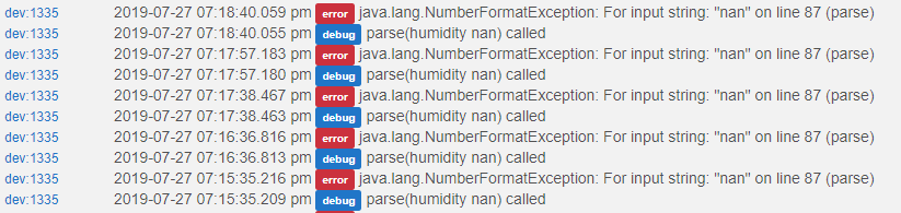
@ogiewon I have one sensor that I am getting this error on. I have two of these that are identical but only see this on one of them. This is the humidity child. Both of these are on a NodeMCU with a BME280 for temp, humidity and pressure and a BH1750 for illuminance. The only difference is that one is in the back yard farther from the wifi than the other that is inside my house. This did not happen at first but started after a while. Is it possible it's due to lower signal?
I believe that error is because the BME280 Arduino library is returning "nan", which means "not a number". This is throwing the error in the Child Humidity Driver as it is trying to convert "nan" to a floating point number.
So, not a WiFi issue. Possibly a wiring issue, or maybe a weak power supply to the NodeMCU board, or possibly the BME280 is defective? I truly believe the problem is somewhere within the NodeMCU and the BME280.
")
 I hadn't really considered the homing aspect of the stepper motors, which, in a typical application which would probably be handled with a limit switch or sensor--ditto for an over travel limit. Clearly, this isn't an arrangement that can easily be incorporated in a blind headrail.