Okay. I've got a few things I might try. But like I said, it works now. At the end of the cycle there's a cool down anyway. So waiting 3 minutes is no big deal. And the heat on cycle will probably be longer with longer loads. We'll see.
1 Like
Hi Ryan,
I joined this thread late however I have a suggestion you might add to the things you are going to try.
This device converts current going through the opening to a voltage.
If you want to get more voltage out of it you can pass the wire you are measuring current on through the hole two times. This will give you a 10A = 1 Volt. Twice the voltage of the normal usage.
It could provide some strange output waveforms but it will absolutely not damage anything.
Unfortunately, that would require disconnecting the line inside the dryer. As it stands, the line going to the wall had about 1/8" between each of the sets of wires. So, with a little patience, I was able to separate the 3 wires without damaging them. The problem is that the voltage output is only 1V and the ADC of my board is 3.3V max.
Also, if the current going through the line is 11A,wouldny doubling it make it 22A? Greater than the max rating of my transformer?
Also, if the current going through the line is 11A,wouldny doubling it make it 22A? Greater than the max rating of my transformer?
Yes that is correct, however in this case the result of over driving your transformer will simply be a limiting of the output voltage.
My assumption was that all you want to do is determine what state the dryer is in, and an actual linear measurement of current was not required. This being so I see two approaches:
- You could send the current transformer to the analog input and read it very fast. For 50 Hz you would need at least: 1/50 * 5 would be better if you could do 1/50 * 10
So really you only have to perform 10 or 20 samples every second or so. I don't think it will be too bad but I've not tried it on your board.
Then you could look through the data, throw away the highest, average the next 3 highest and use that number.
- You would have to build a Rectifier using an opamp. Not difficult but more that #1. However it will yield a measurement capable circuit. I can give you a relatively simple circuit if you want.
The reason the simple rectifier gave poor results is a rectifier drops about 1/2 volt. So your current would have to be 10 amps or so just to make the diode conduct.
John
You didn't answer my question. If the transformer is only rated for 20A, won't 22A burn it out?
Hi,
I thought I had. However to be absolutely clear. NO it will not burn out your transformer. **** The transformer will simply stop putting out voltage after the core reaches the maximum magnetic flux it can handle. What is different in this transformer is the primary is not physically part of the transformer.
Yes that is correct, however in this case the result of over driving your transformer will simply be a limiting of the output voltage.
**** This is not a "I don't think so" this is I am absolutely 100% positive no harm will come to your transformer by over current in the primary.
John
John and Ryan,
The new PS_Power device class that I added recently uses both the positive and negative portions of the wave, and samples the AI as fast as the ESP8266 can in a tight loop (user selectable number of samples in the device constructor) to capture the full sine wave centered around 1.65 volts (0.65v to 2.65v). This device uses the EmonLib library from the folks at Open Energy Monitor, so it should be a decent solution for this application (I hope.)
Like I said, I'm about 800 miles from home atm, and it wasn't really practical to travel with my dryer.  . But I'm gonna try it this weekend for sure.
Sounds like the perfect solution. Easy and (hopefully) accurate 
FYI: I just make a cheap wireless motion sensor, in case somebody need one
Hardware:
nodemcu esp8266
wall adapter 5v power supply (at least 1 amp)
wireless motion sensor
(it is for $ 14.99 but that store regularly have it on sale for $ 9.99)
I just open the receiver, connect the 5v output from the nodemcu to the battery terminals, and there us a little dot market V3, i just connect (solder) the pin from the nodemcu for motion to that dot, upload the hubduino code, and it is working !
thank you Dan for the great library
(I asked in another forum how to use hubduino for IR commands, and ended using the HTTP GET library, and is working now, so i can turn on/off my AC)
(Sorry about my grammar, english is not my first language)
Note: I Just make the same with this:
($20) add two motion sensors ( $9.99 each) and I have a door bell, 2 motion sensor, all wireless for $40
1 Like
So, I'm prepping the circuit for the new library that @ogiewon built (PS_Power).
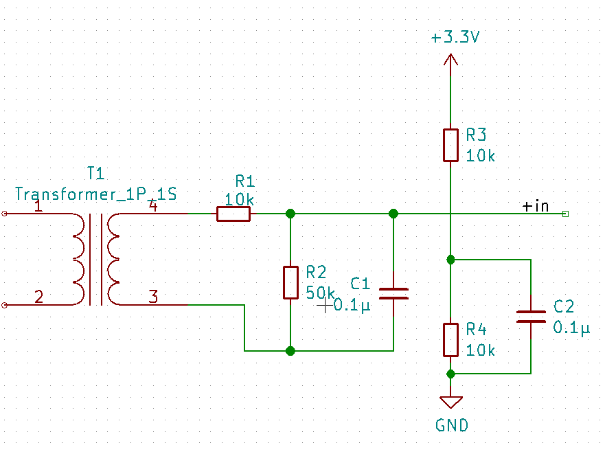
Just wanted to make sure I had it right. I was going to use a cap of 6.3V 1000 uF and resistors of 220 kOhm. The two yellow wires are out to the split core transformer.
As far as the sketch with the new PS_Power library, with my CT I'll use 20.0 as the cal value and 1480 as the sampling. Let me know if you think there's anything I need to adjust before giving it a go. Thanks!!
It likes correct to me.
Experiment with the cal value. I have always been a bit confused by it! ![]()
Also, you may want to bump up the 1480 samples to something higher, like 10000 to see if it helps provide a more stable reading. As long as you don't sample in the tight loop for more than a few seconds, the ESP8266's watchdog should not reset it. Experiment with both values. I am interested in your feedback!
Cool, I will. You think the polling interval of 5 seconds is not too small? Just wanted to make sure that wasn't just for your debugging but actually for use.
If you give me a list of the different combos you'd like to see, I can run it with each of them (as long as it's not too many. Gathering the data is all done by webCoRE and IFTTT so, it's fairly easy to do.
5 seconds is a bit aggressive. But I was just debugging using a variable temp soldering iron as my load. I did not want to wait too long to see a change. For a permanent installation, I would think every 30 seconds would be fine.
If you read through the EmonLib's .cpp file, you will see how the cal constant is used for the Irms calculation. This may help you calculate the correct value for your CT. The 1480 came from the example sketch with the EmonLib. After a little online research, it appears that was the correct number of iterations for 1 second on an earlier Arduino platform. I am guessing the ESP8266 is quite a bit quicker and thus the value can be increased without too much concern. More iterations means more data for the calculations.
Okay. I will give a few different combos a shot. I can tell you right off the bat though that 10000 is too high as I hit the watchdog before even taking the first reading. So, I dropped it down to 5000 and that hit the WDT too. So, I bumped it down to 3000 and that seemed to not give me any trouble with resets at least. The odd thing is, without having the CT plugged in at all (since it connects via mini jack) it's reading 3.9 right off the bat. Probably need to have it plugged in to avoid ghost current I assume. I'm going to go plug it into my CT and see what I get. Wish me luck!!
Good luck!
AS for the non-zero value with nothing plugged in... I saw the same thing. There appears to be an offset as I believe the code assumes (for right or wrong) that the center of the sine wave coming from the CT will be centered at exactly 1.65 volts. That's just a theory, but I know the EmonLib has a 3300mv constant in the code for non Arduino platforms. So, if your voltage divider does not put the center voltage at exactly 1.65v, you might see an offset? Maybe?
In any event, we're going for a relative power change, not an uber accurate reading. Just enough to discern ON versus OFF, right? Hopefully this will work!
Exactly. But if I'm getting 3 with nothing even plugged in, I was just thinking "Is there something wrong with the circuit?" I mean, I know I've got an electric personality but I didn't think I had that kind of current around me! ![]()
![]()
I also found a way to cut webCoRE out of the picture. You don't have to send data to IFTTT in Json format. You can simply use:
Webhooks Integrations - Connect Your Apps with IFTTT[EVENT NAME]/with/key/[YOURKEYHERE]?value1={HE VARIABLE NAME HERE}
You can then store the variable value in Google Sheets. Definitely going to use that more often for tracking certain things.
1 Like
Well, that was certainly interesting....it was definitely able to distinguish between running and not running. When idle, I got values as low as 9. When the dryer was running I got values around 2700! Strange thing is, I was still not able to distinguish between the dryer being off and just tumbling (no heat). And when I ran the dryer in the low-heat cycle, it had the same spread of values, was just at off for a longer period of time. So, it doesn't appear to be any more or less effective than the other setup at detecting the dryer being on/off. And since I already have the other all soldered to a D1 mini proto-board, I'll prolly stick with that rather than solder everything all over again. Although, I will be running a full-cycle later today (it's in the washer now) so I will see how setup 1 fairs and then when I do the next load I'll use setup #2.
On a side note, I have never, EVER, in my life been excited about doing laundry...until now. My mother will be amazed @ogiewon.  hehe
hehe
1 Like
That actually seems a little low to me. 2700 Watts is not all that much. Did you default the voltage to 120 or 240? For the dryer, since you're only measuring 1/2 of the two HOT leads, you should double the result by using 240 as your voltage, This would bring your dryer power usage up to 5400 Watts which sounds more like it to me! My dryer uses 5460 Watts when running.
Oh, I only had it set for 120 since I was only measuring one of the two lines. But either way, it seems odd that I still wasn't able to capture the dryer spinning but not heating. I mean, it's using electricity to spin. I will try to put the CT on the other hot line and see if I can measure it there. Maybe it's only using electricity from one of the two hots to power the motor. I'll also change to 240 in my sketch.
2 Likes

