I added support for the DHT22 in a new branch on GitHub, I tested as much as I could, should work on first try 
So I have been using the christi999 driver for a couple of weeks now and its a very impressive piece of work. Beats the pants off the default driver.
However I am scratching my head over how to use the analog inputs. I want to measure a water tank level via a gauge that puts out an analog voltage level. Typically 2.5 to 7 volts corresponding to level. I set input 2 on the fibaro to analog with internal pullup. The log shows it correctly measure the voltage at 3.08. However I am not sure how to set this value on a tile. What template should I use? How do I get this analog voltage level to be displayed on a dashboard tile?
Any help is appreciated and I apologize if this topic has already been covered.
Interestingly the driver for the input child device still says "Child Digital input". Perhaps that is just a naming thing.
I think the only tile working at the moment is the "Attribute" template with the "voltage" attribute. It just displays the voltage value using numbers. Probably not the best way to display what you want. I will take a look into improving it.
I personally convert the voltage to temperature using an equation and post it as such in the child device but that requires modifying the code...
In the meantime, you could always add a rule in the rule machine to trigger with a change of the voltage attribute of the child and then set the value of a virtual device (e.g. type=virtual dimmer) to a value corresponding to the voltage (e.g. set dimmer "level" = "voltage" X 10: Create a rule local variable, in the rule, set variable to "voltage" X10 then set dimmer level to variable value... ). You can then just use a tile to display that virtual device value (e.g. template "Level Vertical").
I can't find what you see anywhere, can you provide a screen capture?
1 Like
Hey thanks for the rapid support response. I think a big part of my problem is a misunderstanding of what the child devices do. I was under the impression that the two inputs were always accessed by the Child Digital Input driver, and when I set the input to "Analog" that it would somehow switch the reading method for me. I thought that the two Child Analog Input drivers were for the two temperature sensor inputs. However after more experimentation I have realized that the Child Analog Input drivers are also tied to the two main inputs. So when I change the Input to Analog, I should then be reading the Analog Child device. Daahhh....
I'm still learning this platform so I appreciate your patience. For the display I have made use of the new Variable display tiles. I do bit of simple math on the sensor value then display it as a percentage. I have also set the voltage reading to a Hubigraph tile which was surprisingly simple.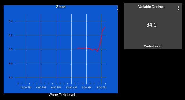
I will also try your method of the virtual device with a vertical level template and see how that goes.
I would like to find a way to change a tile colour if a value is exceeded. Although Im not sure that is currently possible.
Thanks again.
No sweat...
There are a few workarounds floating in the community but I think it is still on the wish list pile for the support in the hub. If you go the rule route, you can always add an extra tile using for example a virtual contact sensor which changes color when open/closed...
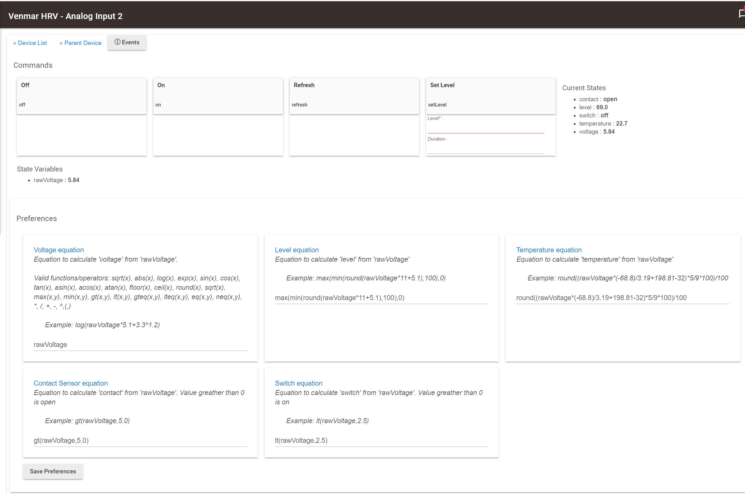
Version 1.7.4 is now available. I had some fun yesterday adding extra "capabilities" to the analog sensor child device such as temperature, contact, switch, level. The values are calculated from the rawVoltage received from the implant using equations entered in the preferences. The resulting values can be used in tiles, rules, etc. Errors in the equations will show-up in the log.
This is a first draft, the switch and level capabilities are not really sensors but actuators. I included them anyway for now. The corresponding actuator commands showing (On, Off, Set Level) are not doing anything.
New to the community here. Thanks for such an excellent driver!
I have my Smart Implant connected to a wired security system.
The two inputs are connected to programmable outputs to monitor the armed status and the alarm status.
Output 1 is connected to a zone that has been programmed to arm/disarm the system when it detects a momentary pulse. I can't seem to get this to work quite like I'd like it to.
Currently, when I turn the switch on, it disarms/arms the security system. However, I have to turn the switch off, then on again to repeat the result.
When controlled by a switch in a dashboard, the same thing occurs. I've tried using Button and Momentary Tiles on the dashboard, but nothing happens when I use them. What am I missing? I'd like to have a button I can press to arm/disarm the system, without having to reset it each time.
Did you configure parameter 156 (Output 1 - auto off) to maybe 10 (1 sec or whatever value you need) in order to create a pulse? You can adjust the pulse polarity with parameter 154 (Output 1 - logic of operation). I just tried it with a "switch" tile, pressed the tile and it works fine, the tile turns on until the output automatically switch back and then the tile turn off...
Sorry, I'm pretty new to all this.
Where do I find these configuration options? Are they in the driver configuration code itself?
No problem... maybe you are using the built-in driver? This thread is for the custom driver developped before the built-in one was available. See picture below for the device's parameter location. Let me know if you need help installing it.

I must indeed be using an older version of your driver. I had installed on 2020-09-05.
To change over, do I need to delete the old drivers and start over?
No, you just need to update the drivers code. However... even with a version from last year you should see that parameter available. If you don't see it then you are most likely using the built-in driver??? Can you confirm which one you are using?
Installing the latest version of my driver is probably easiest using the Hubitat Package Manager.:
Install this code as a new app. Go to the app page and then just follow the prompts to install the latest version of my driver (install/search/"implant"...). This should also work to update from an older version to the latest one.
You then need to go to the device page of the implant and select the "type" in the "device information" to match my driver' s name (user drivers are at the end of the list). Then "Save Device".
If switching from the built-in driver, you would then "save preferences" and then press "reinstall" (select "yes" first). If not switching then there is nothing else to do at this point.
You can then adjust the preferences ,"save preferences" and then "configure", wait 40 sec for the configuration to finish...
You are correct! Although I had your driver installed, I had the built-in driver selected. All is working now! Thanks!
Great!
Dont't forget to change the input/Output 1 - Local Device Protection? and input/Output 2 - Local Device Protection? to "2" in order to decouple input from output, I should make that clearer and maybe change the default value...
1 Like
I do similar to set/unset my intruder alarm system. In order to do this I programmed the 'keyswitch zone input' to momentary (so it's like a spring loaded keyswitch as opposed to a latching keyswitch), I control this using a virtual switch in HE (set to automatically turn off after 2 seconds) with a rule that operates the physical output (your Fibaro OP) when the virtual switch is switched on.
It sounds like your keyswitch input is set to momentary instead of latching too so you might need to do this.
Hey thanks for the updated driver. I have an application for the analog level calculations which are currently done using rules. I have not switch over yet but it is on the todo list. In the mean time I have another issue:
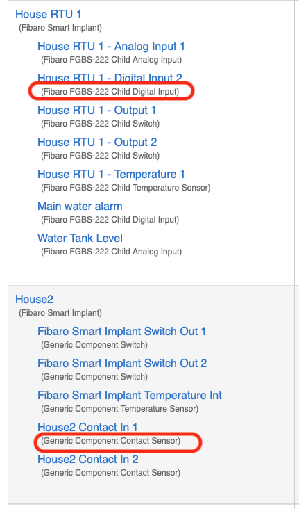
I have just included a third Fibaro 222 implant and all seemd fine. As usual it popped up with the default Fibaro driver. I then tried to swich to the Christi999 driver. I did it the way I did before which was to select at the parent. In the past this should have populated the child devices with the new drivers but it has not. Have tried several times. I hit save then configure. The log is showing it configuring, but the child devices still show the Generic drivers. I have excluded and reincluded but still the same. Has anyone else found this? Am I doing something wrong? Do I need to do this manually now?
The attached image shows the two units with different child drivers.
OK forget all of that. I just hit "Reinstall" and that fixed it. I guess I must have done that with the other ones but forgot. Kind of weird how it take the parent (config) driver without a reinstall but not the children.
Just a word of caution for the less experienced on this platform like me. If you do decide to upgrade to this very excellent driver all of your rules, tiles etc that reference any of the child devices will be broken and you will need to rebuild them. So make sure you have your rules etc documented.
1 Like
I wanted to do this for some time and your previous posts gave me some incentive to finally do it...
The child devices are created and controlled by the parent's diver code so when you change to a new driver for the parent, it doesn't have a direct way of reusing the child devices created by the previous parent (e.g. the child's driver code be incompatible, difficulties finding which old child device is what, missing/extra child devices, etc. ). This might not be too bad in this case since hubitat's driver uses "generic" devices but I didn't investigate that approach. I added the reinstall command to clean/erase them and start from scratch. So yes, you will loose anything attached to them.
The same thing will happen every time you use the reinstall command, even if you don't change the driver type. I guess I could add a warning to that effect in the command description.

