Thanks for your response. Here's what I have
Please explain about your powersupply. I is not common for 5V power supplies to have a green wire.
As for wiring:
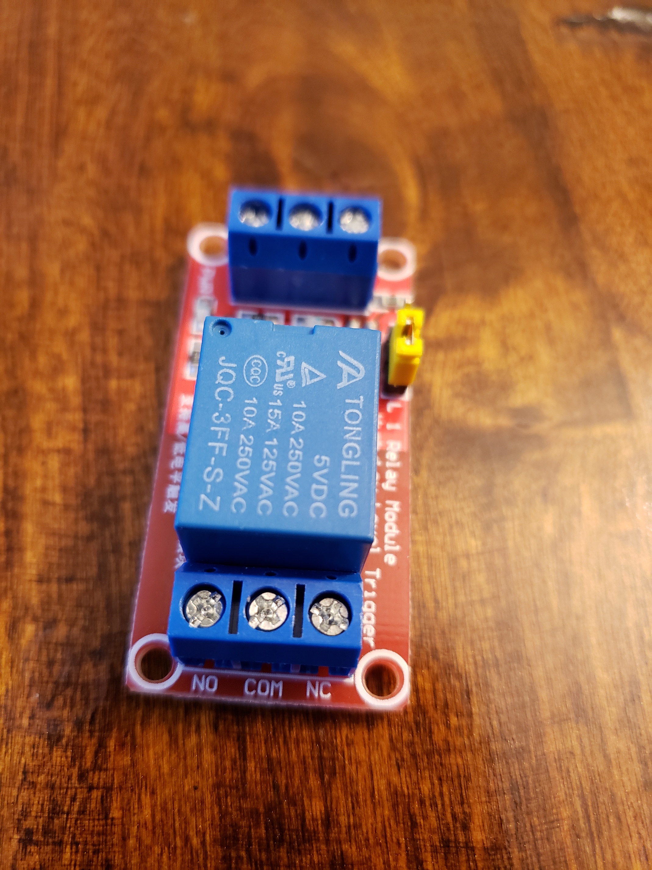
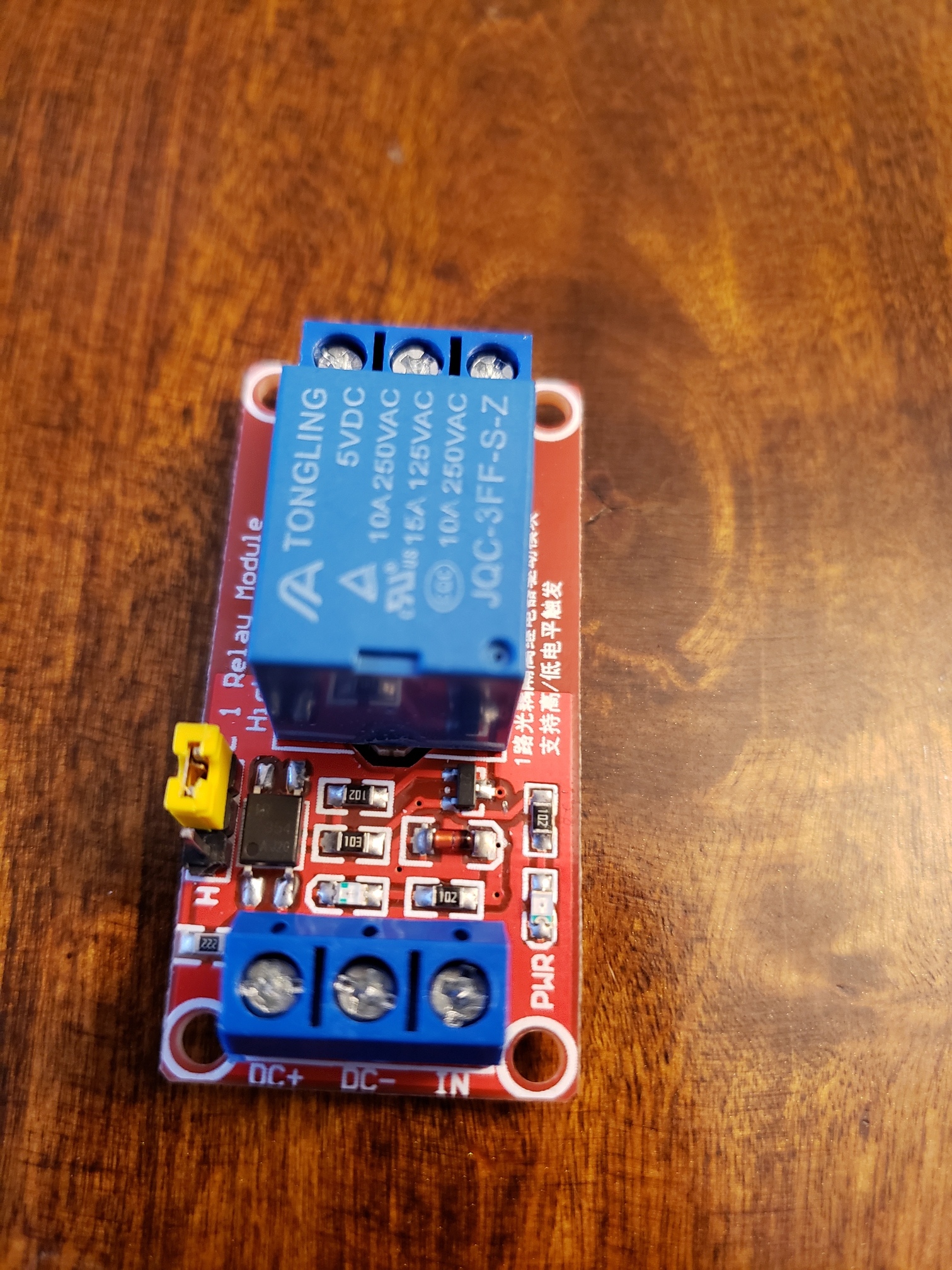
Your relay looks like this one ebay relay.
You would connect you 5v Powersupply:
- the + (Red) of your power supply to the DC+
- the - (black) of your power supply to the DC-
- you would connect the IN to DC+ ( you should hear the relay "click" when you connect power.
John
Thanks. I will do that. My power supply was a micro-usb cable. I cut the micro-usb port and that's when I saw the four wires.
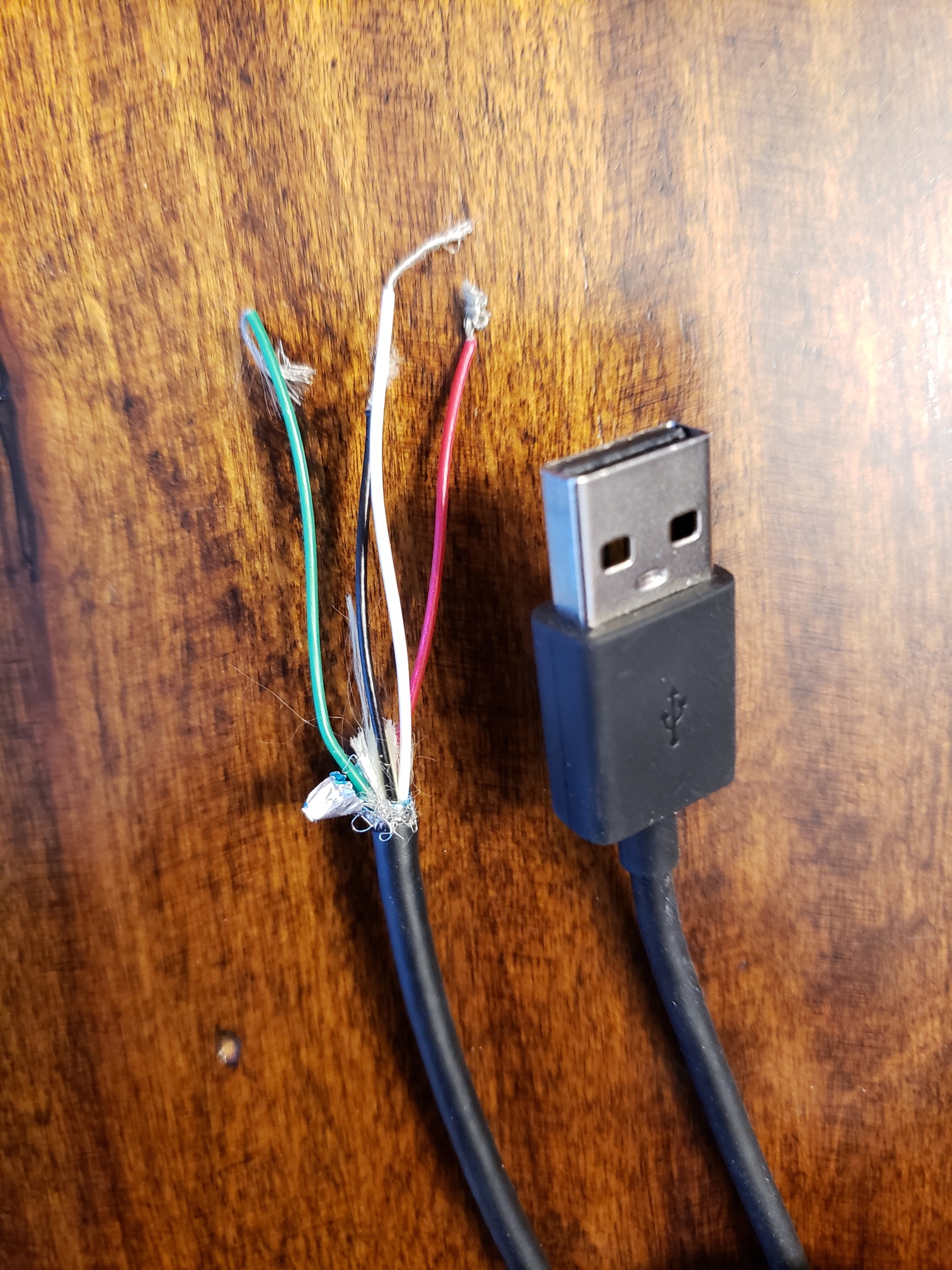
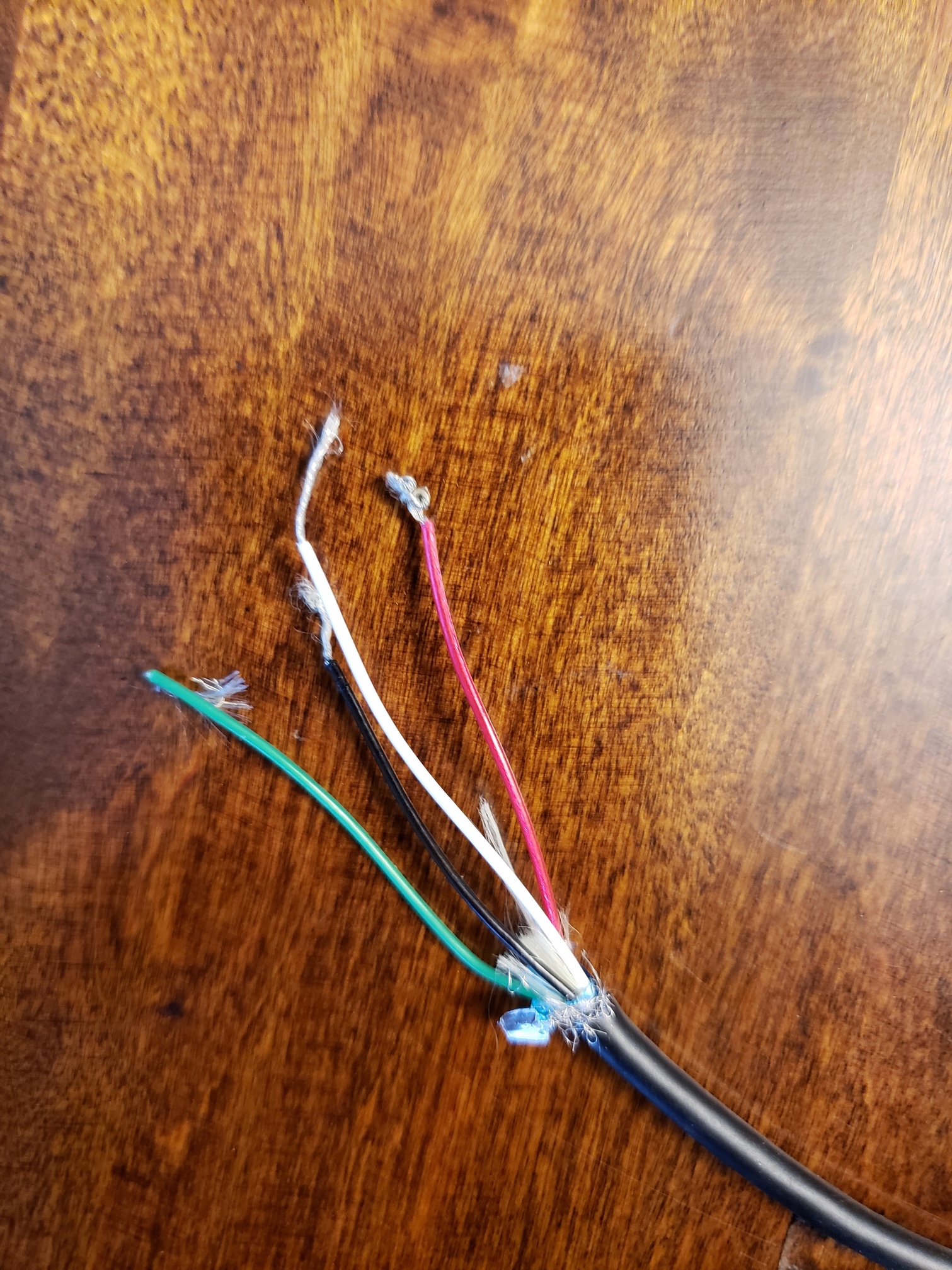
OK .... here the green and white are the data lines from the USB. I would cut the stripped part off of them and tape them up so they don't short to anything.
3 Likes
How will you be monitoring the output of this relay? What are you wiring it to in order to monitor it? This relay requires two 5v inputs. One into the DC+ and one into IN when you want the relay to be on. So, you could try to wire the red wire to the DC+ and then a jumper wire from DC+ to IN. The black would go to DC-
1 Like
And does it work?
Yes! We have pretty consistent power, so I have to test it occasionally, just to make sure.
It was a quick, fun project.
3 Likes
@JohnRob, @ritchierich, @Ryan780, thank you for your responses. I was able to try it out, and it worked great!
3 Likes
Question, What are folks planning on using the Power out Signal for?
I was thinking of a poor man's UPS/Shutdown for my Hubitat. It is a very simple approach to simply send a signal to the Hubitat (from any of the above mentioned contact sensors) to shutdown due to loss of mains power.
I'm just not sure its worth the effort. We've have had a few short power outages in the last 3 months but none effected the Hubitat database.
Both of my Hubitats are on UPSes. One of them is plugged into the same UPS as my Odroid, so I use the Odroid to shutdown the Hubitat when power is out and there's 15% capacity left on the UPS.
However, the other Hubitat is plugged into a different UPS. Building a power monitor was cheap (cost about $10; and I had several unused contact sensors) and took all of about 30 minutes. In contrast, getting another Odroid/RPi and configuring it to gracefully shutdown my second Hubitat would: a) cost a lot more; and b) take the better part of a day.
I've had database corruption once, and I was unable to restore a backup until @bobbyD helped me out (on a Sunday evening at that!). I figure that $10 is worth avoiding the effort it took (not to mention the accompanying anxiety).
1 Like
I also turn all my lights back off 5 minutes after power is restored if I'm in Away mode. All your smartbulbs are going to come back on at 100%. If i'm gone for a week on a work trip, that's a lot of kWh I don't need to be paying for.
2 Likes
Thanks for the motivation. I start collecting parts 
Hmmm.... I started to describe my approach in this post and when part way through I realized I hadn't accounted for the current draw of the hub when it has been shutdown. Oh well more design thought is needed.
Or that we should be burning fossil fuels for .....
Eh...yeah...the planet I guess too. But the big motivator is the wallet. 
2 Likes
I use one of this to monitor my car remote starter and a few to shut down my Pi, computers.
Greg, sorry to poke you so long after you posted this, but if I can impose.....
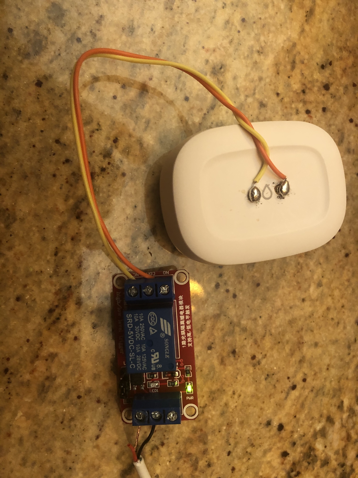
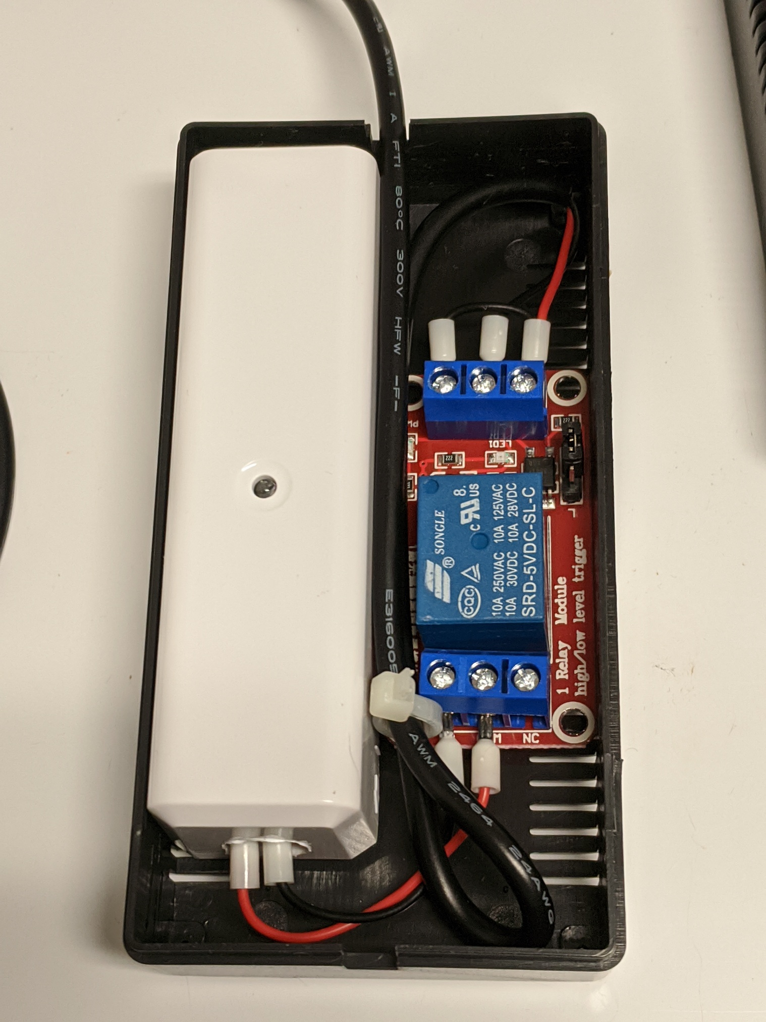
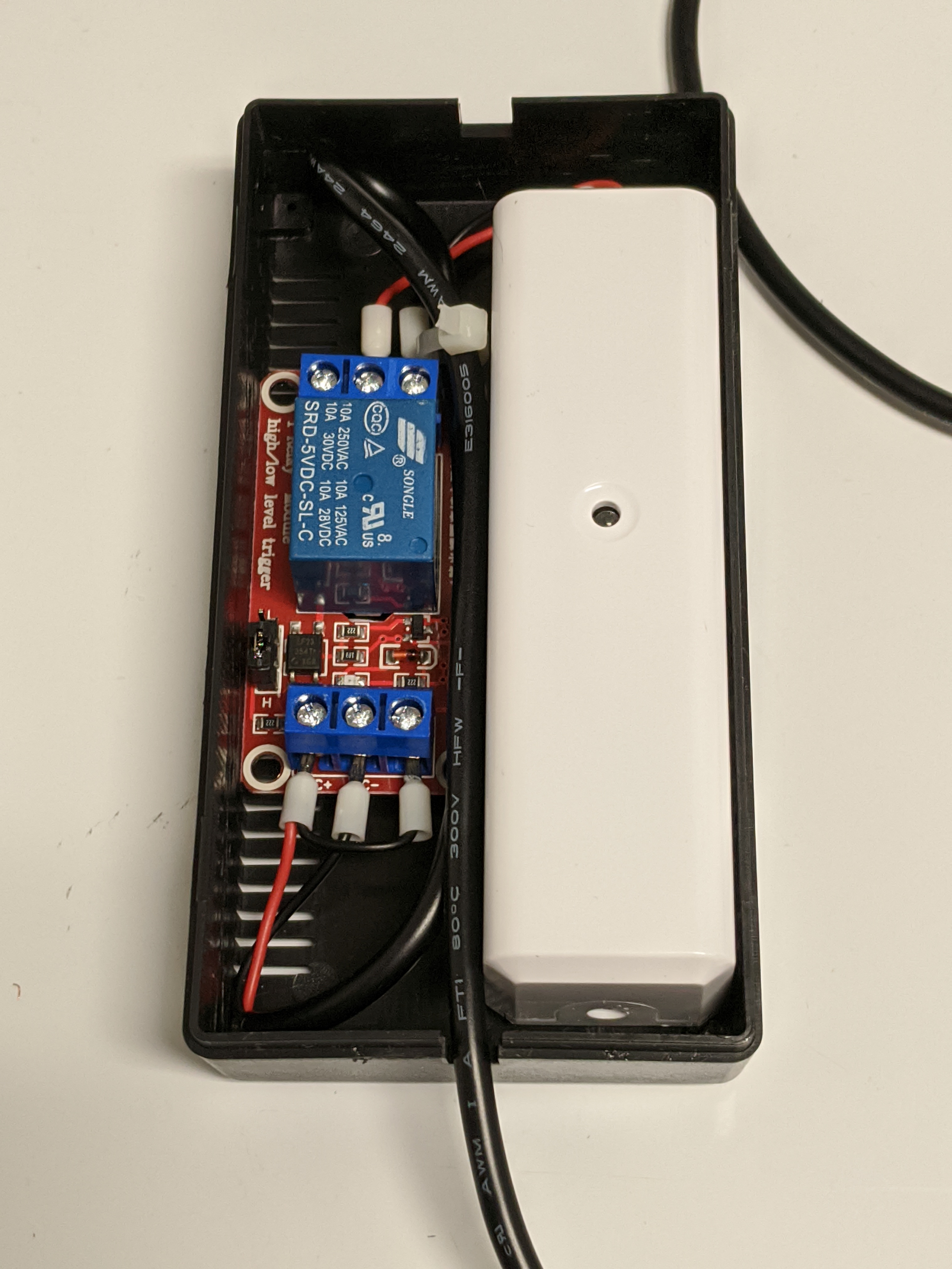
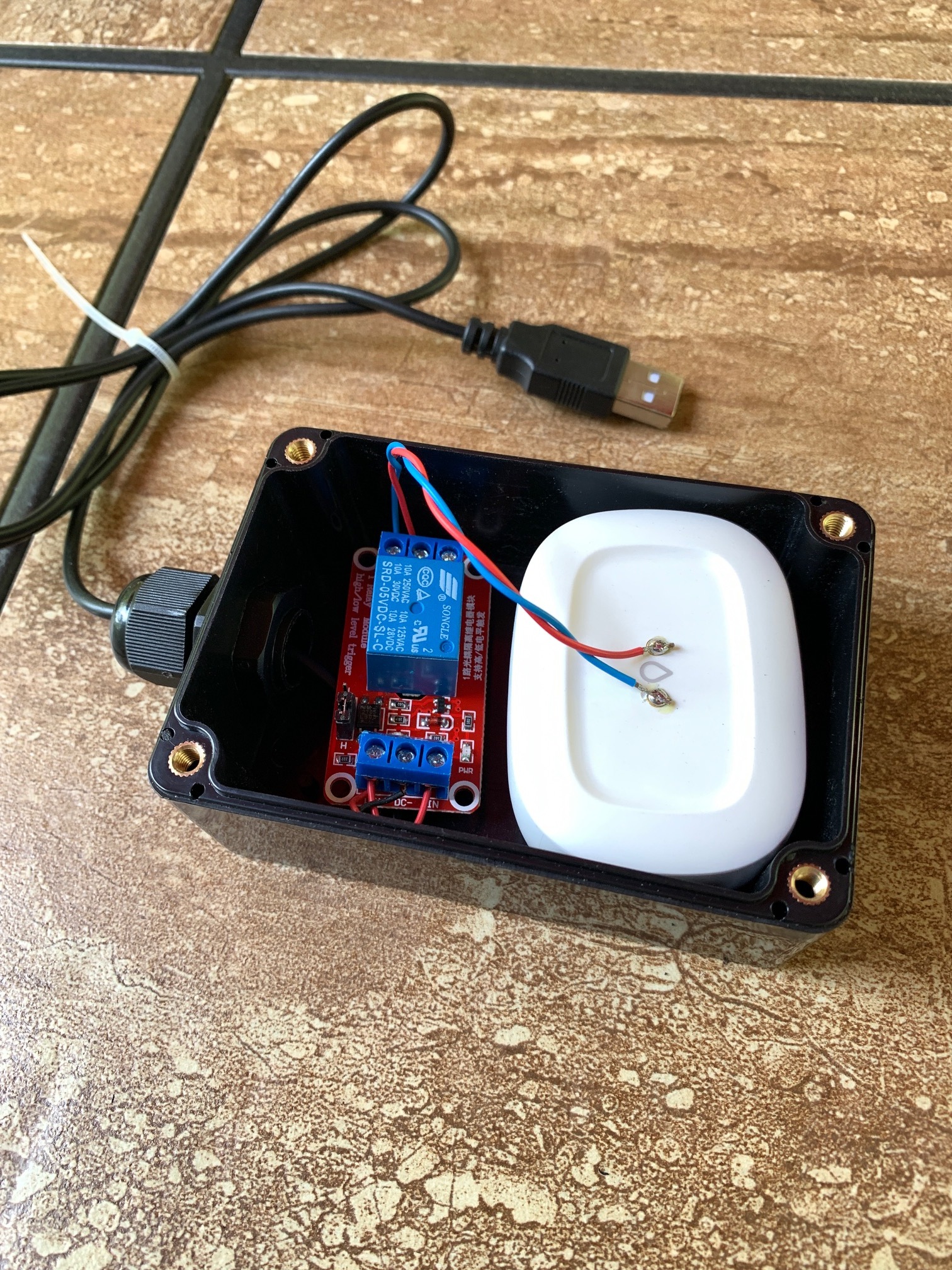
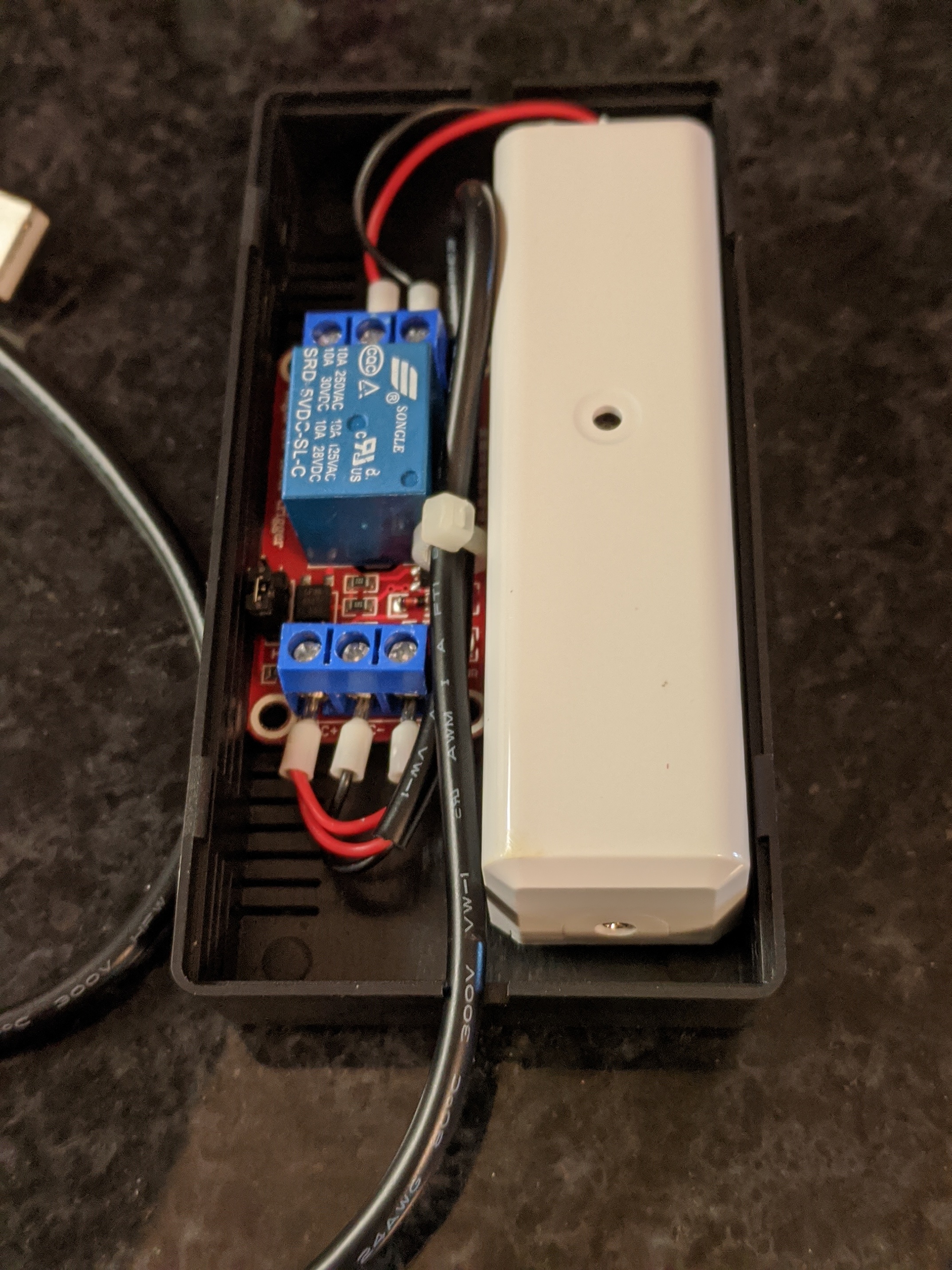
I had the same spare parts as you, so I gave it a go today. See pic below. I soldered one pair of wires to the ST water sensor contacts on top and then connected the other side to NC and common contacts on the relay.
Then I stripped a newer apple power cord and connected red/black to the DC+ and DC- contacts on the other side of the relay. The relay LED indicated that it was powered.
However, whether or not the Apple power is plugged in, the device shows Wet. I can get it to change to dry, but only if I disconnect one of the wires between the water sensor and the relay, which makes no sense to me.
In your picture, it’s difficult to see the connections between DC power and the relay so I can’t quite tell if I’m mirroring your setup properly. Any ideas?