Do you have a recommendation for the 24V Addressable LED strips with their clips that Pixelblaze can control?
Here is my quick Amazon search (but there are many similar others):
Scroll down a little bit and you will see Clips and Power Supply
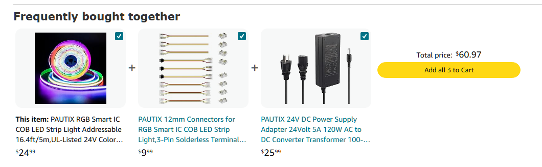
5A PS should be OK.
This strip does not have a dedicated White LED, only RGB but my experience with COB RGB color blending is very good (however not everyone is happy with just RGB without dedicated White).
Also you may need a wires (something like this, but make sure to chose 3 conductors):
For powering Pixelblaze you will need DC-DC downconverter.
There are very many different but for example here is one with screw terminals:
And of course you will need a Pixelblaze (chose a pre-soldered one with 3-PIN connector and what is very important - with disconnected Red Power Wire):
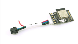
That wire needs to connected to the output of DC-DC converter.
Before connecting Pixelblaze to the DC-DC converter you need to tune output voltage to 5V. Otherwise Pixelblaze will be instantly damaged.
To make sure everything is working as expected my suggestion is to connect all components together before cutting a strip into pieces .
24V wires from the PS (polarity is important!) must be connected to the input of the DC-DC converter AND power injection wires of the strip. Output of the DC-DC converter (already tuned to 5V before connecting to the Pixelblaze) should be connected to the red power wire of Pixelblaze.
3 Likes
Thank you so much! I’ll go ahead and get this to play with them ![]() wish me luck
wish me luck
I hope, you will be very satisfied with Pixelblaze controlled LED lighting.
There is a very nice HE driver for the Pixelblaze. The control is 100% local.
Please make sure to use a DHCP-reserved IP (recommended) or configure Pixelblaze with Static IP. Otherwise you may step into lost connectivity.
and one more time reminder, please make sure Pixelblaze is powered ONLY by 5V PS.
Please check https://electromage.com/ web site.
They have a lot of very useful info.
GOOD LUCK!
1 Like
I'm finally getting around to messing with this and I just realize that I accidentally got the 4-pin connector:
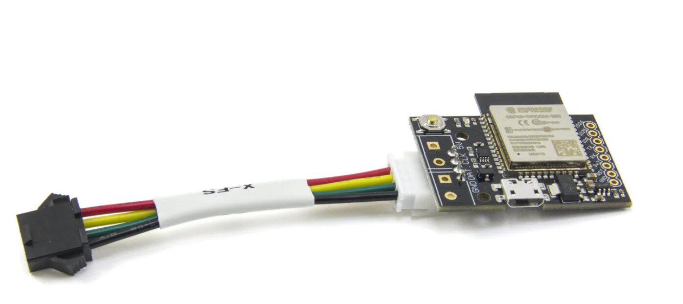
Is it possible to convert it into the 3-pin and disconnect the Red Power Wire?
Certainly you can cut off a Red power wire. But unfortunately you cannot physically resize a connector. If sodering is not a problem you can forget about connectors, cut them out and soder wires directly to the pads. Otherwise you will need to buy a correct adaper wire or use a wire coupler.
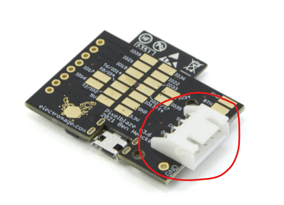
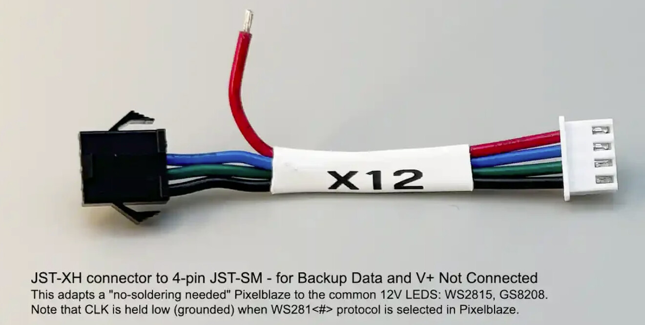
The problem is not electrical. The problem is mechanical. LED Strip has 3-pin connector but what you got as well as X12 adapter terminated with 4-pin connector. Unfortunately these two will not mate mechanically. If soldering is not an option you certainly can use wire coupler.
Oh that's what you meant. I do have some crimp connectors I could just use on the wires. I'm a little confused about powering the LEDs and the PixelBlaze. I know you mentioned that I need a DC-DC Step Down Buck Converter set at 5V, but the LED strips themselves need 24VDC. I have a 24V/5A Power Supply. Do you split the Power Supply: one 24V going to LED strips and another to the step down converter? Or should I just use a separate 5V Power Supply for PixelBlaze?
Basically you need two power supplies: 24V DC for the LED Strip and 5V DC for the PixelBlaze.
PixelBlaze needs only 0.5A current.
So, for the LED Strip you already have AC-DC 24V/5A. Now for the PixelBlaze power you can use either DC-DC 24V-to-5V downconverter (this will be my preference) or AC-DC 5V power plug (something like USB 5V adapter will work) but in this case you will need two outlets (not convenient).
Now about wiring.
- PixelBlaze GND, LED GND, PS -24V and PS -5V (Input- of 24/5V downconverter if used) circuits must be connected together;
- PS +24V must be connected to the LED +24V and to the Input+ of 24/5V downconverter if used;
- PS +5V must be connected to the PixelBlaze 5V pad;
- And finally PixelBlaze Data pad must be connected to the LED DI circuit;
I know picture is much better but right now I dont have drawing tool handy.
1 Like
I drew the wiring diagram yesterday and this is what I came up with also, but I wasn’t sure what the best way to connect the wires together without soldering. Do you just use twist on wire caps or Wago connectors? I also read bad reviews on the step down converter I bought that output voltage creeps higher than what is displayed (after testing with voltmeter) ![]() so maybe I’ll just use a separate PS-5V for the PixelBlaze
so maybe I’ll just use a separate PS-5V for the PixelBlaze
Does these look right?
Separate 5V Power Supply:
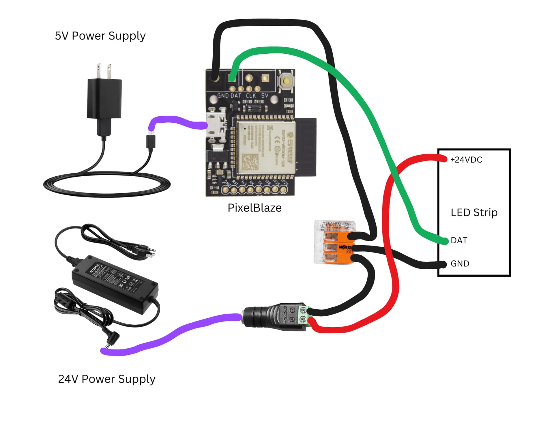
5V DC-DC Down Converter:
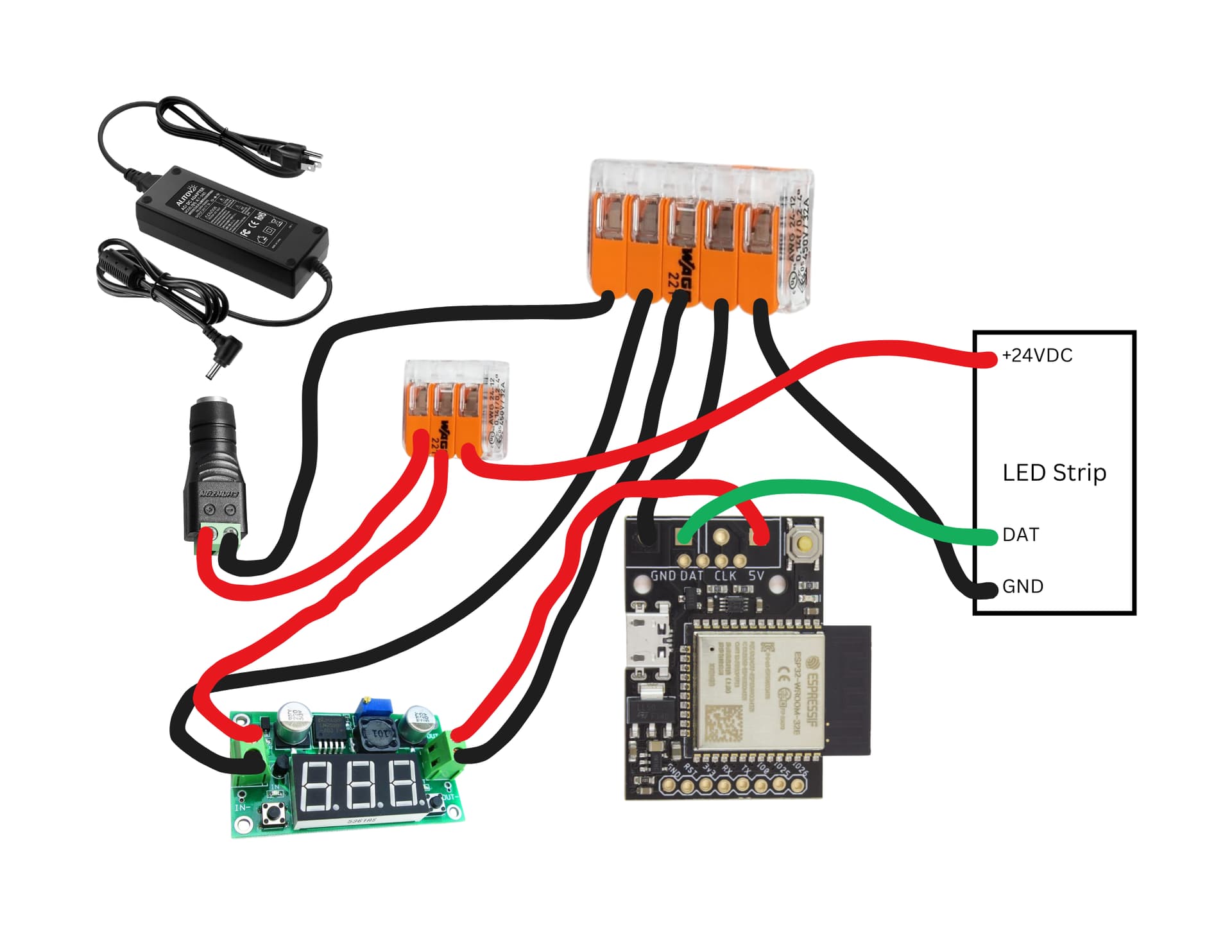
I was not sure about the Output GND of the downverter.
I am EE and of course, my preference is soldering. Wagos are very good for 10-14 gage wires but too big for the 18+ gage wires. Small wire cups could be a good choice.
I am/was using similar dc converters without any problems but voltage setting is/was done by multimeter. PixelBlaze can tolerate upto 6V and I guss, 4.5V is a required minimal voltage. If you don't have a multimeter around and don't trust the built-in one you can set voltage to say, 4.75V. I hope it never will be over 6V. So PixelBlaze should be happy. And of course, you can use a separate 5V ps and even utilize a USB connector on Pixelblaze. But in this case please make sure nothing is connected to the 5V pad.

