Giving a detailed setup on how to set up a Fibaro Smart implant with Hubitat. I'm not going to get into soldering, wire ties and those things of that nature. However, you should have enough detail to accomplish the task.
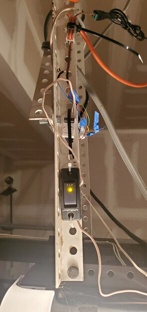
Below is my setup. Quick and little messy but it works!
List of main parts:
-
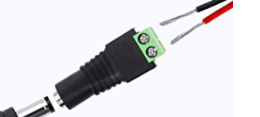
ALITOVE DC 12V 1A Power Supply 1000mA 12W AC/DC Adapter, 100~240V AC to DC 12 Volt 1 Amp 0.6A Converter with 5.5 x 2.5mm 2.1mm Plug for LED Strip Light CCTV Security Camera DVR NVR Surveillance System NOTE: Screw block for adapter (female)
-
FIBARO Smart Implant Z-Wave Plus Plugin Universal DIY Tool, FGBS-222, doesn't Work with HomeKit
-
Security+ 2.0 Wired Dry Contact Adapter - www.garadget.com: They will do the light if you ask (not part of these directions)
-
Garage Door Opener with Security+ 2.0 – Sears, Liftmaster and Chamberlain (required: you should have this already)
-
Hub C7 (required: you should have this already)
-
Tilt sensor/Door Sensor
Note: The Fibaro Smart Implant has very fine wires be careful of this and DO NOT Power on until ready
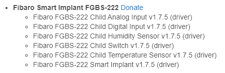
I pre-downloaded Smart Implant device drivers. I used HPM (Hubitat Package Manager Application) to do this
First you need to install the button on your garage opener. If you purchase this pre-wired, then red (+) wire will connect into the Garage Door opener on the motor side. If you have a button, you will connect it where that one is by the motor (connector location). White (-) wire will connect into the Garage Door opener on the motor side. If you have a button, you will connect it where that one is by the motor (connector location). If you push the button, that you have just connected then the door should open and close. It may take a few tries due to Security+ 2.0 needs to sync with the button the first time
Don’t worry about the other wires (speaker wires) from the button yet. Now if you touch the two ends together it will open the door (that is what the Smart Implant will do).
Don’t connect the Smart Implant connector into the Smart Implant, yet. We will do that later.
Note: I extended my leads from Smart Implant with something a little bigger and longer (I soldered; you do you).
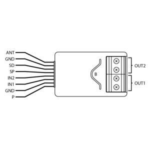
Look at Smart Implant Image. below
Connect Red (Implant wire (P)) into the (+) side of the adapter. Connect Blue (ONLY 1 Wire (GND) into the (-) side of the adapter. Tape the tips of all the other wire EXCEPT for the Black (DON’T cut anything). Black is the antenna.
Smart Implant Image
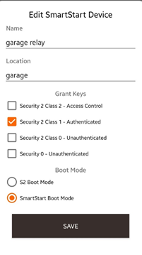
In C7 hub I did the QR Code with the Mobile Hubitat software and set it up like:
Connect the Fibaro connector into the Smart Implant and be careful of direction. See above (antenna on top and blue & red at the bottom)
Now, connect your Female connector to male connector for the AC adapter. You should see an LED light come on. Wait for inclusion. (Read directions)
Once, you have this included into your hub go to Devices> Fibaro Smart Implant. Select the user DLH that you had installed above: Save then you should see Install or Reinstall (yes)> Save again. Once this is completed, back at the Device page it should look like this.
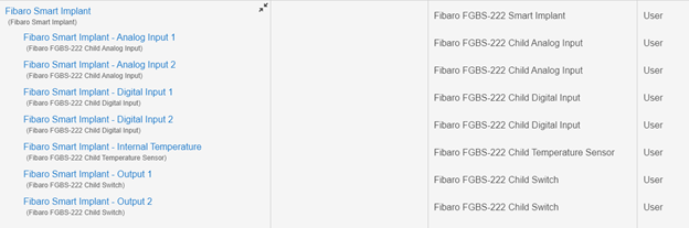
Verify that Fibaro Smart Implant- Output 1 can turn on and off (I didn’t install on the opener until I was done). [If you have the light lead on your button, follow similar direction to get that to work too for Output2]
Now go back to parent device (Fibaro Smart Implant) go to setting options “Input/Output 1 - Local Device Protection” set that to 2 and Save. Then go to “Output 1 - auto off” >5 (this worked for me but maybe not for you; higher is a longer time for on before it is turned off) Save and then Configure.
Note: Sometimes it takes a couple of tries for that setting to take effect or seconds.
You can repeat Output 1 verification again, but it will not stay on this time it will turn on and then back to off. (Auto Off is now configured)
Once this is done you are going to connect the speaker wires from the button to the OUT Put 1 on the Smart Implant (make sure it is secure and the wire insulation is not in the way from making contact with screw block connection. This doesn’t have polarity [(+) or (-)]. Make sure you connect it correctly in Output 1 correctly.
Now verify, that this all works. If you repeat Output 1 verification again now the door should open and close.
I’m not going to go through the Garage Door apps but as long as you have a tilt sensor or door contact then you are ready to move on to the Garage Door Apps.
I hope you all find this helpful. Thank you everyone for your help over the years.

