Iman,
I just received my sensor and was able to easily pair with with Hubitat. So far, so good. Thank You!
One question - If I want to reset the device to be able to pair it to another hub, what is the procedure?
Iman,
I just received my sensor and was able to easily pair with with Hubitat. So far, so good. Thank You!
One question - If I want to reset the device to be able to pair it to another hub, what is the procedure?
heres what i do to deal with that:
def getHubType()        {
    if (!state.hubId)   state.hubId = location.hubs[0].id.toString()
    if (state.hubId.length() > 5)   return 'ST';
    else                            return 'HU';
}
then when i need to act on ST vs hubitat like for you in the parse method:
def hT = getHubType()
if (hT == 'ST')
   do this
else if (hT == 'HU')
   do that
Hi Dan, Glad you can play around with it. Please use the latest DTH, I just update them. There is an issue if you want to adjust your temperature value.
To reset, there is a push button. I have instruction here.
You can remove it from the hub as well. The hub will send zigbee disconnect command which will reset the sensor when you have a chance to remove the device.
The hardware momentary button on the above instruction is needed if you somehow want to force reset it without doing remove device from the hub GUI.
Thanks!!!!. I will learn how to use this. I am hoping I can get the 2 codes merge back with that technique.
ok.
what module and software do you use for that?
thanks.
I just tried using the three user preferences in the driver to adjust the temperature and humidity. It doesn’t look like these adjustments are working on Hubitat? Can anyone else confirm, one way or another?
if you use Xbee module, you can use xtcu from the xbee module.
I just have a fix checked in on github. May I have you try the latest one on the github?
BTW, give the sensor sometime to settle down before you make adjustment.
Iman,
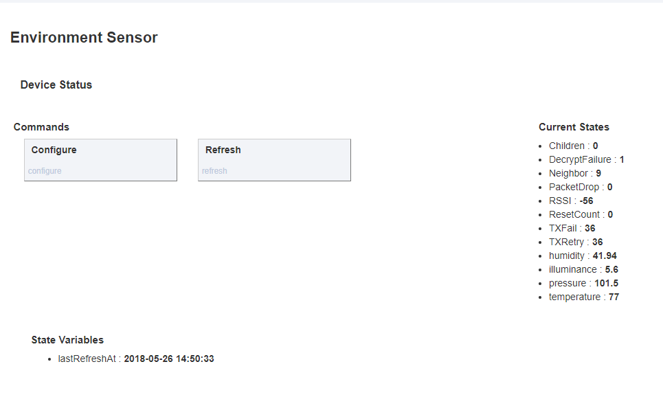
I just tried your latest driver version and temperature and humidity are now working as expected. 
One more question... What should the range for the illuminance sensor be? Mine varies from ~0.0 (finger over sensor) to ~64 (bright flashlight shining directly on the sensor).
Thanks,
Dan
Which Xbee module (i.e. part number) would you recommend to use with XCTU to show a map of the Zigbee network?
Hi Dan, The TEMT6000 is sensitive to human visible light. In term of lux, I do not know what those numbers are. There is an information for Lux calculation in the datasheet. That is how I got the lux value.
How I use this number is more of relative measurement. I did just like what you did. I had the room in pitch dark and get the minimum value. Then, I have it on reasonably high ambient light to get the max. I, then, use the two value as min and max value in my app to do my businness logic.
I have s2c Xbee for my other project. They work fine with XCTU. I heard Xbee part number is very complicated. I got them from ebay. It just say S2C.
Iman,
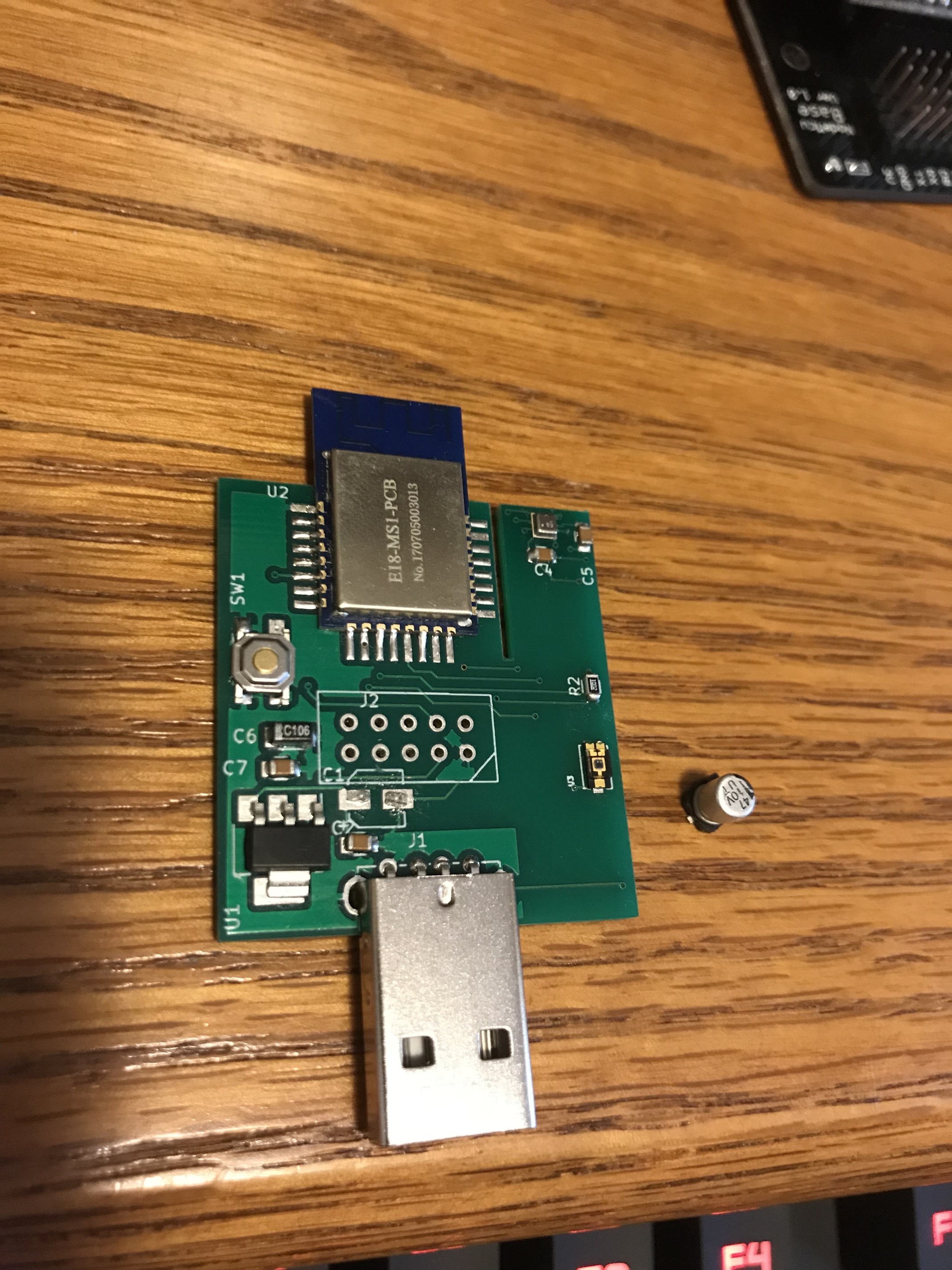
I just discovered that a capacitor was broken off the board in shipping. I just found the capacitor in the packaging materials. What is the purpose of this capacitor? (see image below)
Can you please advise me on how I can reattach this to the board? I am pretty good with a soldering iron, so I might be able to perform the repair. I would need to know what the proper orientation is for the part.
Thanks,
Dan
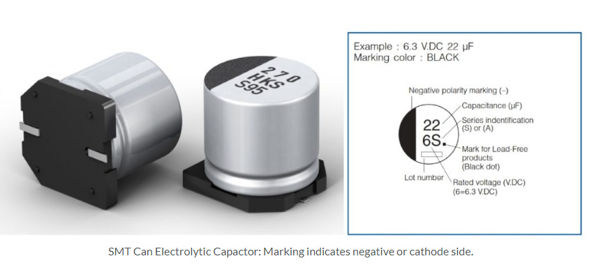
The side of the cap with the black mark Should be + and you can see + orientation in the board
Sometimes, a picture is worth a thousand words...
Unless Iman tells me not to, I plan on reattaching as shown in the picture above.
 And I’m wrong. Good call.
Lol. You’re a kind fellow. I knew it indicated + or -, but backwards is wrong and you would have known it when you tried to use it and wasted your time soldering it in wrong based on my feedback.
Dan,
If you have soldering iron, you can try to attach it as the picture on ST forum.
All capacitors are by pass capacitor. I am planning to remove them when they are not need. The bypass capacitors are recommend per chip bases. I do not want to take a risk and I followed manufacture recommendation as is. In reality, based on final board size they may not needed.
This particular capacitor is for low pass filter on the ldo input line. I am kind glad this broke. I know now that I may not need it. This is one of the more expensive passive component. If I can get away without it, I would not include it on final board. Thanks for letting me know.
@bangali yours has different ldo. Yours do not need low pass filter.
@ogiewon you may not need to reattached it especially if your usb power is stable. The sensor is very low power. They are unlikely cause dip on voltage with any reasonable power brick. However, if you really want it, you should reattached it.
Download the Hubitat app