from the picture you gave, the red and white wires are for the door (the other 2 are for the light) you'll want to tie your ZEN16 into the contacts with the red and white wires (do this at the board level), then it will simulate pressing the button. this will trigger your door. you can put it in parallel with your existing button as well, so both the existing and this new one will function. that's how i have mine set up and it works
i'll take a picture of mine when i get off work later and post it here for you
sorry for the multiple post, the last one was from my phone.
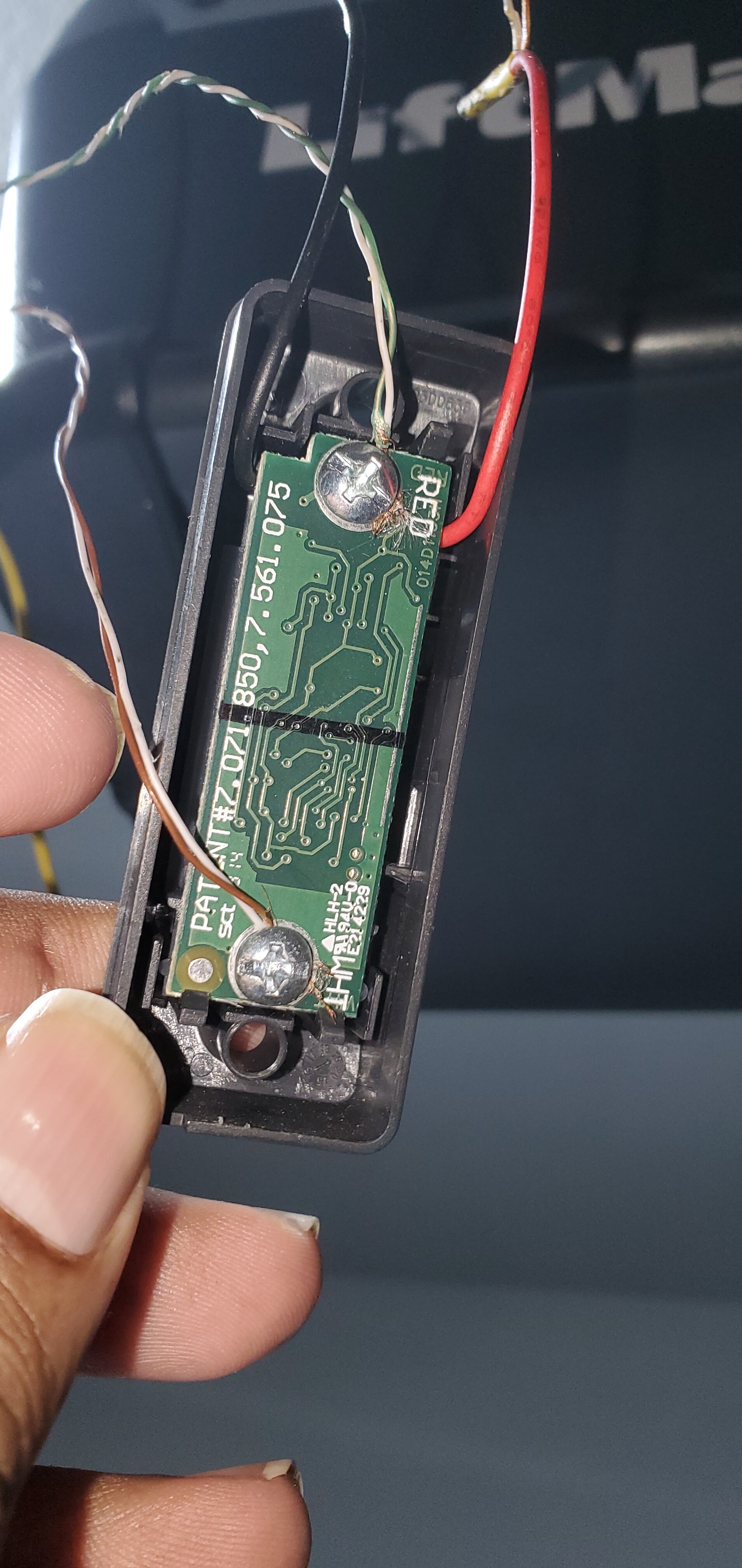
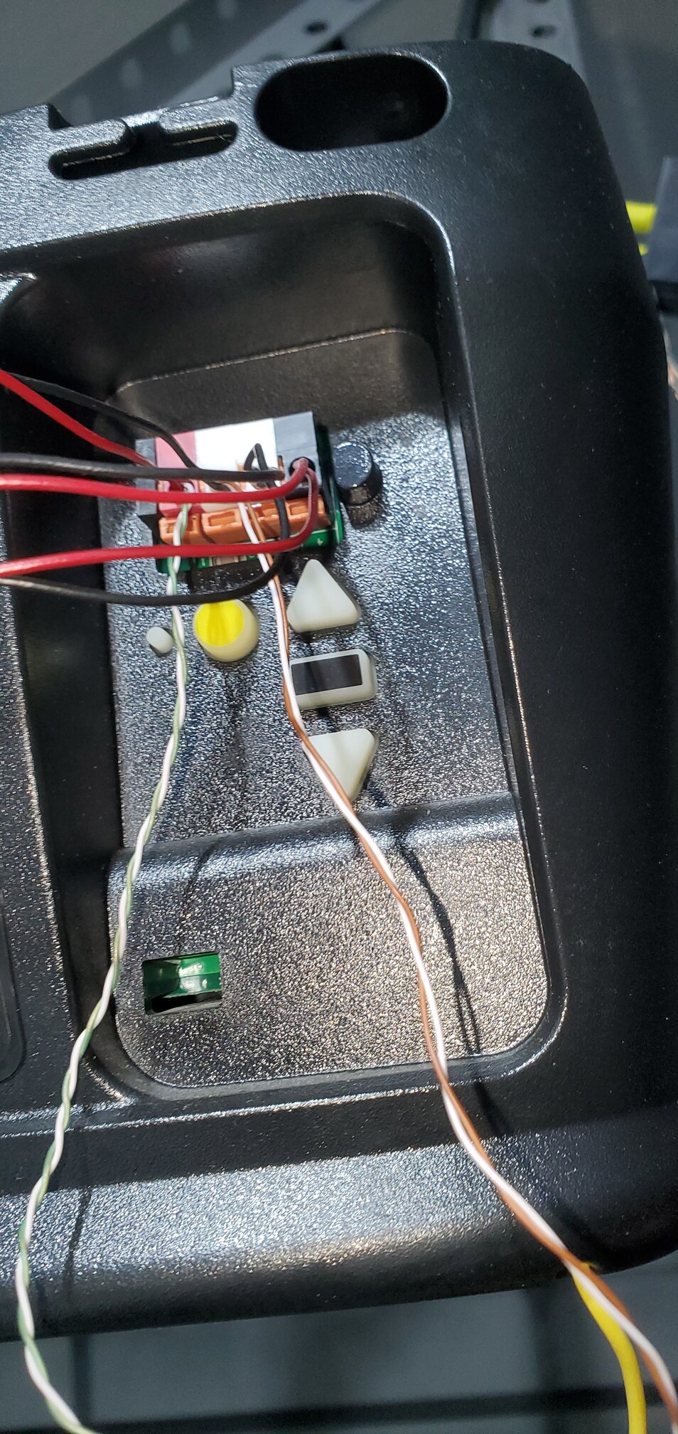
so in the first pic, the red and black wires are soldered onto the button (used a multimeter to help me determine which pins shorted when it was pressed), then that goes to the relay. the twisted pairs go from the red/white connections and into the motor in parallel with the existing button. both work no problems
no. you would connect the clear wires (based on the pre-wired pic) from the button into R1 (or R2), so when you activate the relay it'll activate the switch. the red/white wires go to your motor
the button will give the security code so it'll activate the motor. if you go directly from R1 (or R2) to the motor, nothing will happen since it does bridge the connection, but it won't receive the security so it won't do anything
Ahh.. Now I get it. The two R1 points when triggered are connected. This makes the new switch think the button was pushed. Which then send a signal from the new button's Red and White connections to the garage door motor.
I know this is an old thread but I wanted to add some information to it that worked for me.
@dadarkgtprince I used your guidance to wire up the opener. The wiring was simpler then I thought from the wiring diagrams. Just like suggested I soldered two wires to the existing Liftmaster switch at the board level. As you said a multimeter can be use to determine the two pins that complete the circuit when pressed. I have the simple security code switch with light control. I then ran those two wires to the Zen16 relay 1, normally open connection. That is it! I have a single switch, no need for an additional purchase.
Perhaps I misread but for those of us with the secure code switch it seemed like we needed to purchase another switch with dry contact lead. I know some may not want to solder so that may be why the new switch is suggested.
For some who do want to solder just note, this is uber simple, two wire setup. All existing control of the light is retained. I have the Liftmaster 8164W.
That's part of it. The other reason for purchasing an additional wall control or remote is to facilitate mounting the control and relay at the head of the GDO where you already have power and a good place to strap it down. In my case, I already had a pair of bell wire running to my wiring closet from there.
This topic has more recently been discussed at topic below, so that may be a better place for any follow-up.