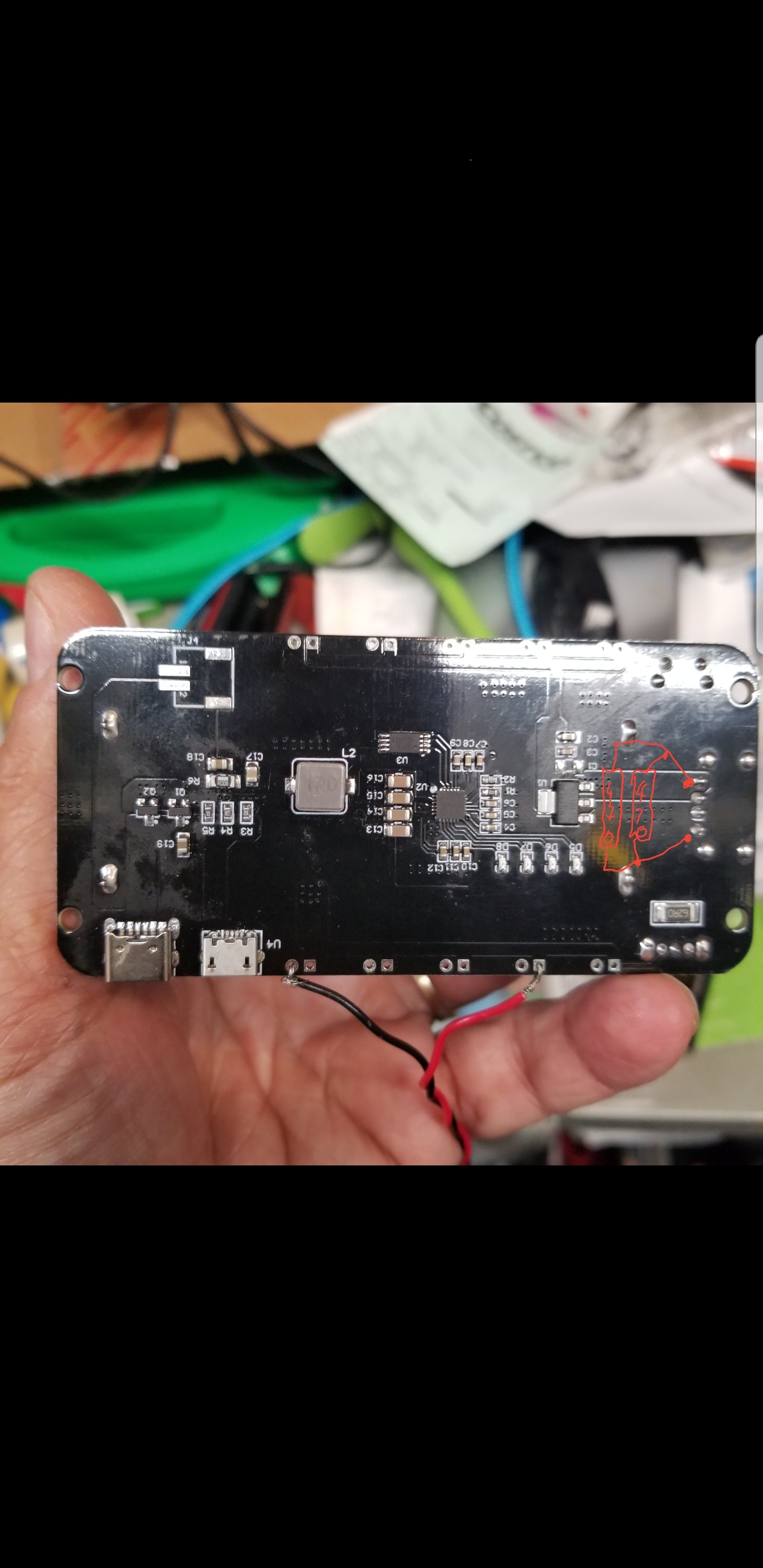
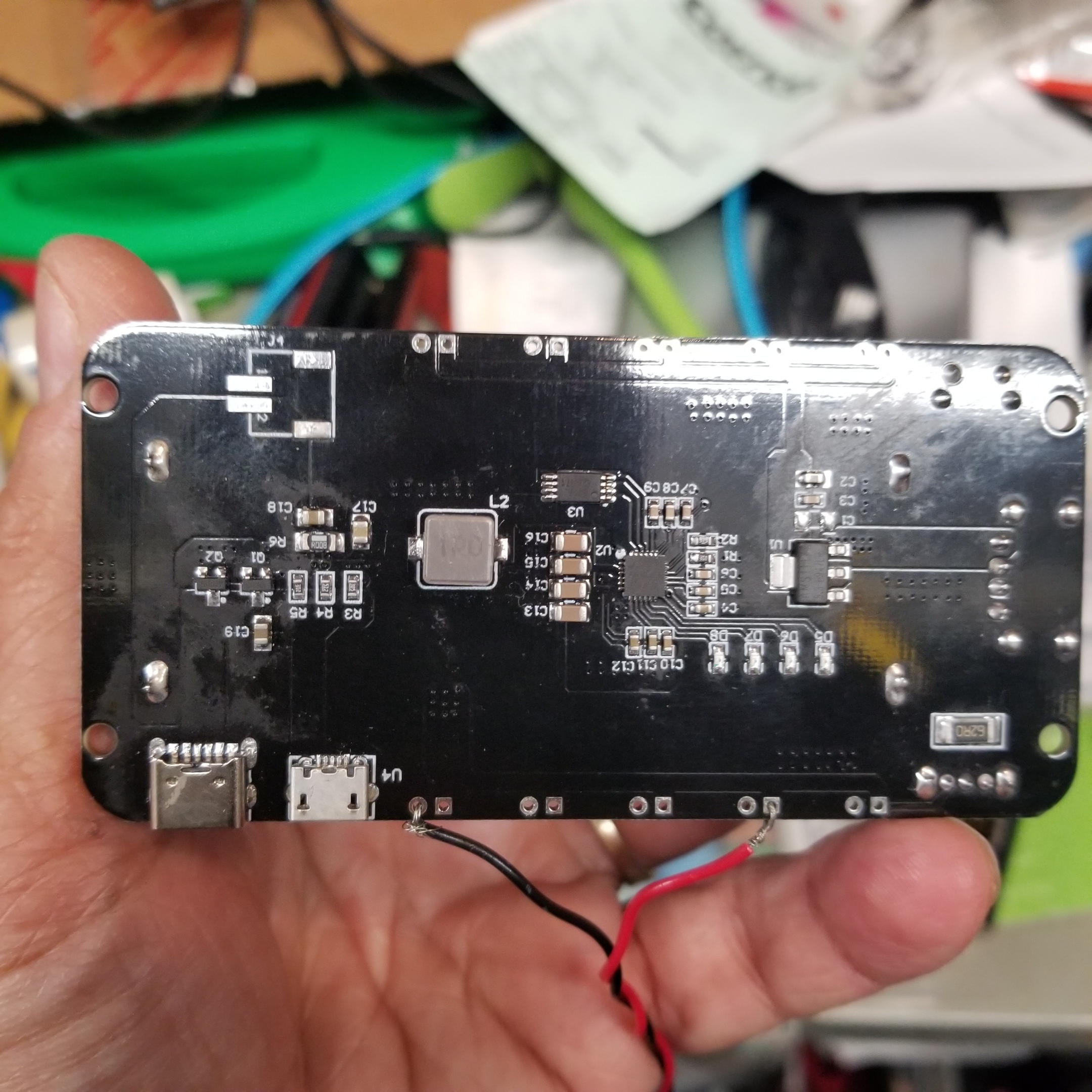
I have one that looks nearly identical (except R6 for me is square instead of round, but what I assume is the part number written on it, "3R3", is identical). That is the only board I have tried that works for me, with again one of the most notable differences being that it has a physical power switch/slider rather than an apparently "soft" power button like the others. I wonder if that has something to do with this all, too.
Did you buy yours from the link in the OP?
I bought 4 and 1 was a complete dud, the other 3 work great.
Have you tried putting a couple of 470 microfarad electrolytic capacitors (in parallel) across the output to take up the slack while the battery kicks in?
I got mine from AliExpress instead of BangGood, apparently just taking my chances. The one that worked for me was the "module" version of this listing, though presumably the "with cable" variety would be the same (but on another listing these two variations were actually slightly different boards and neither worked): https://www.aliexpress.com/item/32911096857.html?spm=a2g0s.9042311.0.0.62d74c4dEM00Ok (again, that's the one that worked for me).
Ordinarily, soldering would be way out of my abilities, but it actually looks like there might be enough surface area and enough space between them on some of my non-working boards for me to stand a chance of success. ![]() Still not sure I'll get the nerve to try it, though. I've found some that would work well for the hub, and these would still be useful on USB repeaters or other things that wouldn't mind a quick power blip.
Still not sure I'll get the nerve to try it, though. I've found some that would work well for the hub, and these would still be useful on USB repeaters or other things that wouldn't mind a quick power blip.
1 Like
R6 is actually the small part to the right or "R2". What you are referring to is L1 mine is square as well.
The two different boards (the one you are running and the one with the 32 pin IC) are of a completely different design. The buttons have entirely different functions.
The switch no your board simply turns off the 5V output to the USB connector.
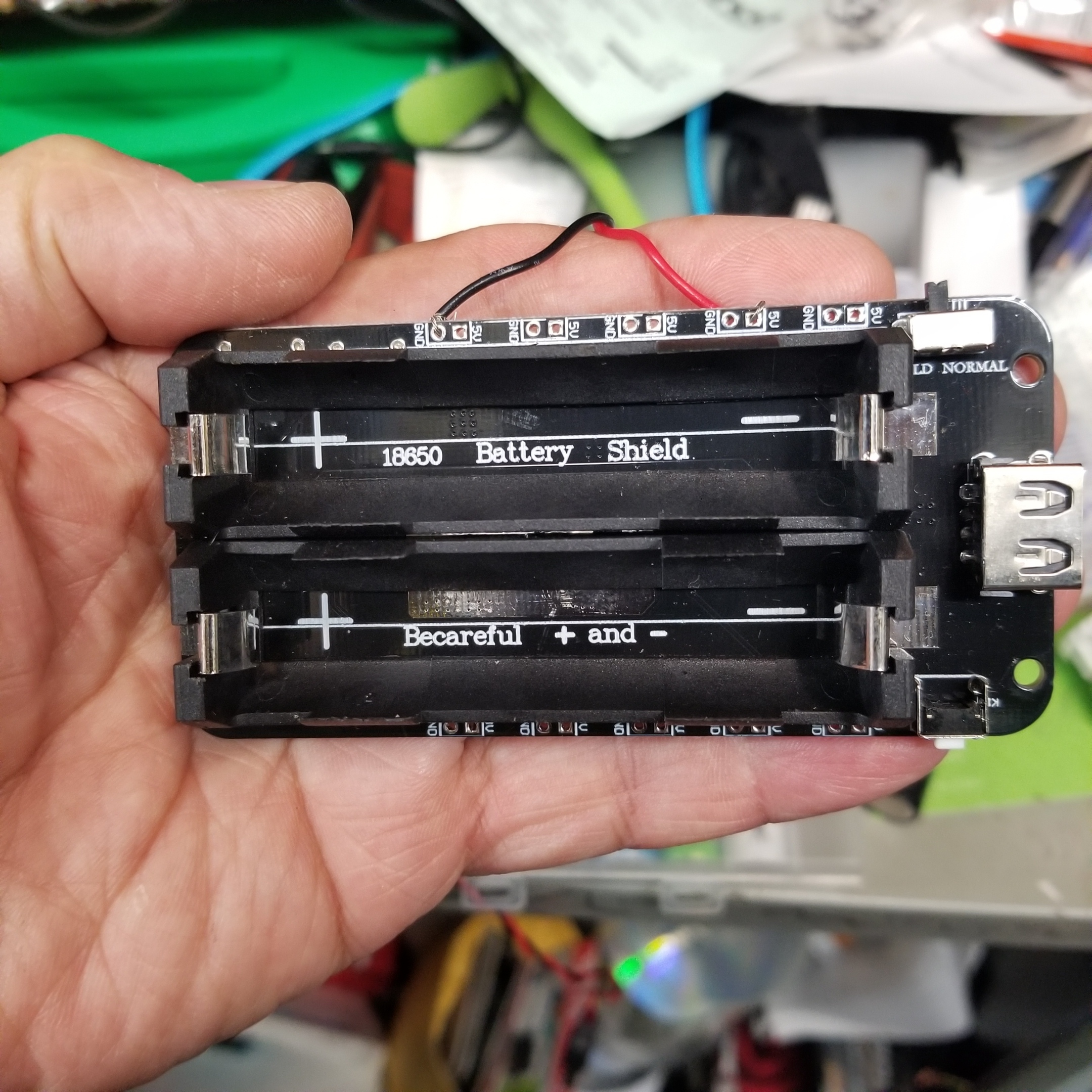
The LEDs are important.
The RED = charging the battery
The GREEN = battery is fully charged.
You didn't mention the LED color. So I suggest.
- power you UPS board with no load. The LED will likely be RED.
- Wait until the LED is GREEN then connect your load.
- Perform you remove power test.
If you have a multimeter and wish to continue I'm more than happy the help you figure out what is going on.
BTW I lost track of the start of you post. What load are you using? A Hubitat?
John
I have never seen the LED turn green on any of my others (there's a series of four that I assume roughly indicate level and are probably fully charged or at least >75% when the stop blinking?), but I'll leave them plugged in longer this time and see what happens. ![]() The board that works well for me only has a single LED. I don't recall the color, but I guess I wasn't as concerned since it worked off the bat.
The board that works well for me only has a single LED. I don't recall the color, but I guess I wasn't as concerned since it worked off the bat.
I've tested with various loads--usually not a Hubitat, but since that was my ultimate goal, I did try a couple times. I've mostly used a USB power meter/tester and also tried an Xbee (where my best guess as to whether it reboots is if its LED stays on, which it didn't). Results so far have been the same with all.
I do have a multimeter but can only be trusted to use it with careful instruction. ![]()
OK lets focus on the board that works. The one WITHOUT the 32 pin device.
Follow the sequence from my last post and we'll see what happens.
John
This is blue on all of my boards.
Same here.
OK then looking a the board on post 184
L1 = Battery fully charged
L2 = Battery charging.
So we had a 12.5 hour power outage starting last night at 11:20pm - my setup using the Wemos board as a UPS worked perfectly, as did my power failure detection system.
When I got up at 6am to check things, my Hub had powered down to the red light automatically after 6 hours, and the Wemos Board had not yet run out of juice. Happy days. 
2 Likes
My bet would be pouch cell's as they are cheaper than 18650's.
I thought that but the description says 12 x 18650
You are correct, I didn't read the details. ![]()
The more important aspect is WHO made the cells inside. If they are LG, Samsung or panasonic, you'll get a very good long life out of them. If they are generic chinese cells, then life could be substantially less. My unsubstantiated guess, based on price, is not top notch cells, but I could be wrong. 12 cells x 3.00(bottom price for 1000+ quantities samsung25R cells) is $36.00, then add the circuit board, case & shipping. That would leave about 10 dollars profit.
Anyway for 61.00 it's not bad.
On a side note, I just redid my dyson battery pack with 6 x 18650 Samsung 25R. The runtime is now amazing, and at 1/4 of the dyson price.
I have no problem replacing cells as needed. I was really just curious what the inside looked like if anyone had any pics. I like to see what the insides look like before I go ripping them apart. I have a ton of spare LG and Samsung 18650's laying around.
1 Like
Hey Tom, please see my 3rd grade art. Is that how you're saying to connect the caps? And would 700uf allow more slack in terms of longer projection from blips?
Out of curiosity I plugged my C7 and battery backup into my Power meter and boy is this thing efficient!!! It positively sips power - on average it's drawing 1.6 watts with the occasional spikes up to 3.8 watts when the battery has been drained a bit and is being charged.
At 1.6 watts (0.01A), that's only 0.0096 kWh's of energy used in 6 hours!  Even at the worst case of 3.8 watts power draw (0.022 A), that is only using 0.0228 kWh's of energy in the same time frame!
No wonder a 3,500 mAh battery can run for 6+ hours without issue! 

1 Like
Should be able to get a couple of days out of mine then.
2 Likes
Bought one of these single battery versions. Works treat had to make a custom box for it so put some plugs into it. It’s not pretty but it’s out the way and works 
2 Likes

