This is the relay I used. Yes the green power light turns on. I did have to use a 10k resistor even with this relay so that the button on the LCD controller still works. But when I press the button on LCD the power to the relay is terminated. I even tried using a USB 5V power to power the relay and connected one of the sides of the button to the "In" terminal and nothing unfortunately.
Ahhh... Now I see why you are using the 10k resistor. It was not for the EOL but because you connected the relay coil parallel to the switch. The resistance of the coil is very low. Less than 1 ohm and this is the same as having the circuit closed.
Try connecting your relay in series.
Dan I am trying to debug via serial monitor in Arduino. I uncommented the Serial.printX lines in the callback function and all I am getting is this type of stuff:

I would also like to see the analog read values if possible too so I can adjust the InterruptSensor.cpp file accordingly. I added Serial.println("analogRead: " + analogRead(A0)) to the file and it wasn't coming out in clear text either. I also tried the following that I saw in other cpp files but got a compile error that F wasn't declared:
Serial.println(F("analogRead: " + analogRead(A0)));
I am sure I am missing something simple.
Looks like the Serial Monitor Window is not set to 115,200 baud. That should clear up the text.
To print the text with a value, I usually use two lines of code:
Serial.print("analogRead = ");
Serial.println(analogRead(A0));
but your string concatenation might work as well.
Dan thanks. After my post above I realized I may have a bad board as I had 115,200 set and then soon there after my Arduino IDE locked up. 
1 Like
@ogiewon and @Navat604 Success!! Thank you both for your suggestions.
After taking a week off at the beach, giving time for replacement ESP board to arrive, doing a little research, and coming home and trying a few things I got this working.
My ESP board will be in my crawl space so I need to run to my local container store to buy something to put it in since it’s quite humid here in NC. I will post pictures and details once that is done. Thank you again!
2 Likes
Awesome! Glad to hear it is working.
1 Like
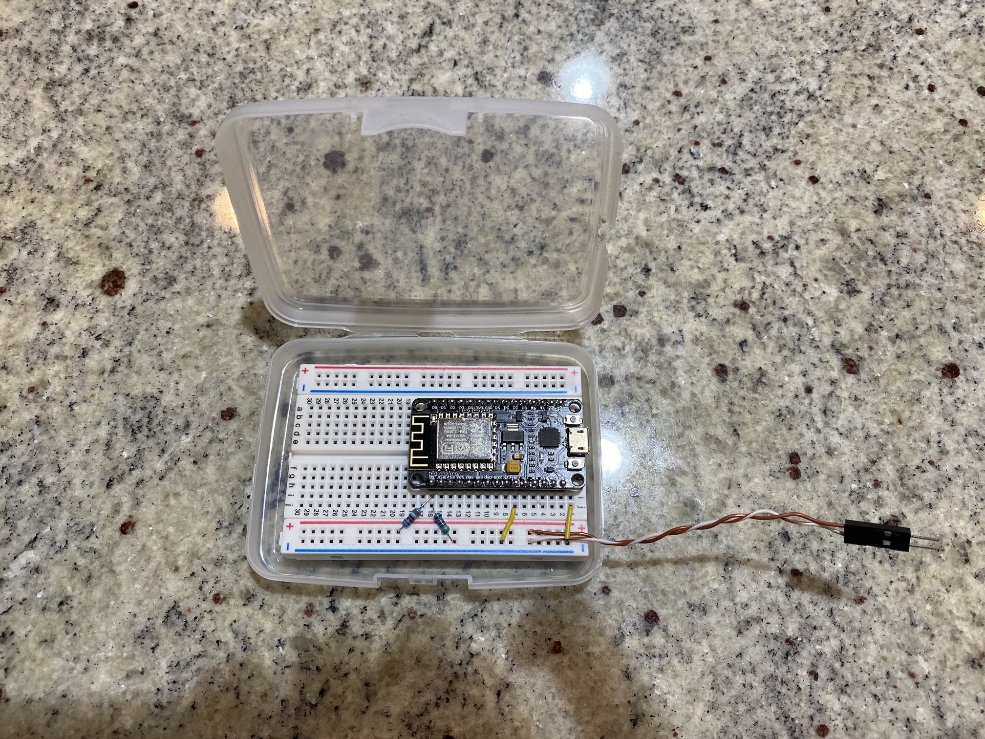
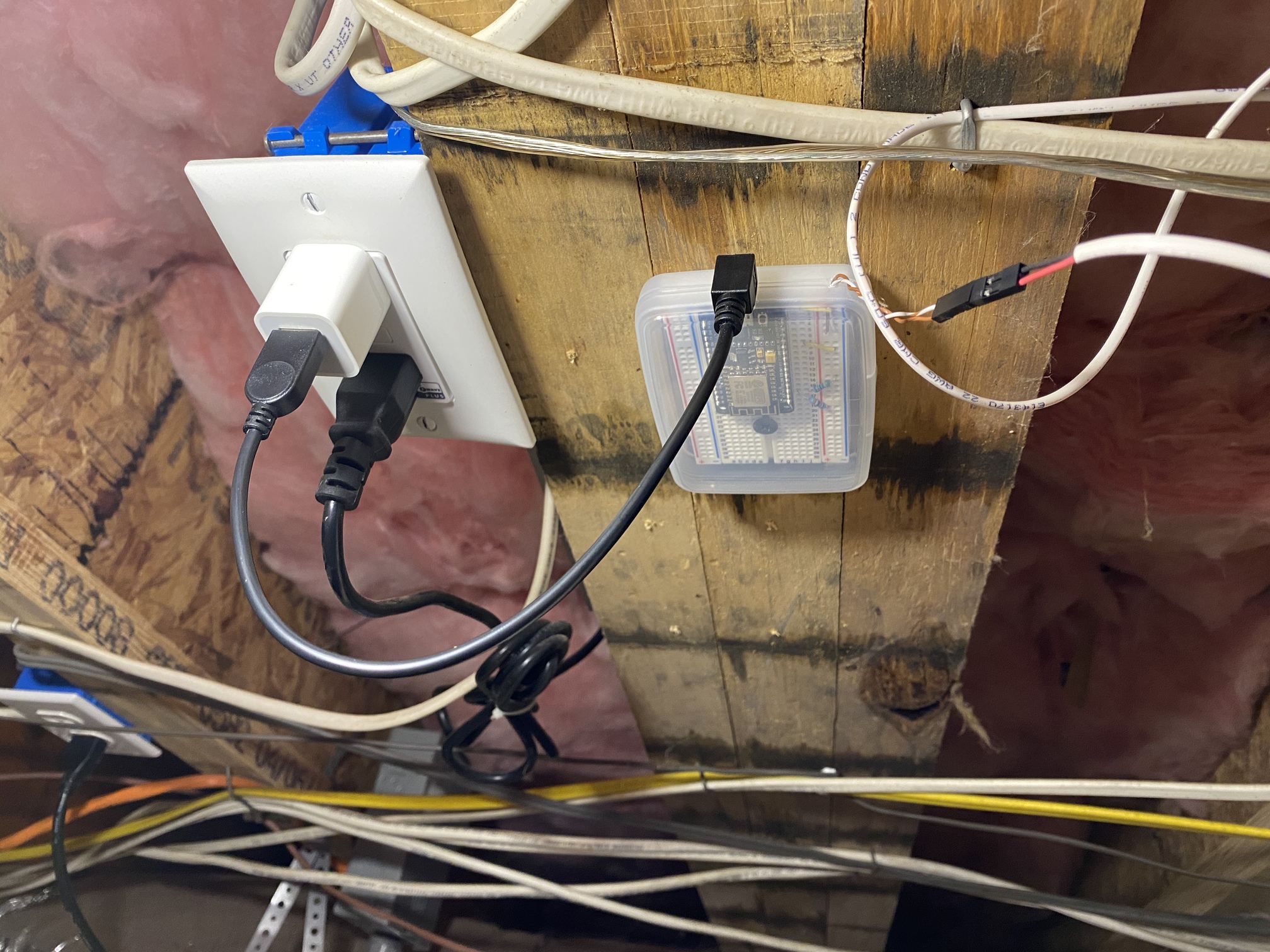
Here are images of the final solution.
- Used two resistors to create a voltage divider to reduce voltage to less than 3.3V
- Connected ground from the ESP board to ground from the button so there is a “common” ground to measure voltage
- Put breadboard and ESP board in a plastic box purchased from the Container Store since this is in a humid crawl space to protect from elements
1 Like
Very nice!
Thank you very much for you and your sons efforts on Hubduino. Awesome library that made my custom app so much simpler to know when my circulation pump is on.
1 Like
This topic was automatically closed 365 days after the last reply. New replies are no longer allowed.

