Any way to manually add a child device to an st_anything/ESP8266?

Cool - I'll update the driver code.

The sketch does indeed work. I've already constructed several working units.

It is basically a small, very low cost, battery operated switch device. The esp8266 wakes up from low power mode, tells the Hubitat that "contact1" is on then off again (toggled) and then goes back to deep sleep. That way I can get quite a long time of usage on a 3.7v 5000mAh Li-ion cell.

I've also constructed them in a more standard config with a power supply plugged into the wall - but I prefer being able to be cordless so that I can place them in areas that might not have an AC wall plug.

I know the code is a real hack-job, But it does work in deep sleep mode just as intended!

The only reason I've had this problem (this post) is that for some reason child creation has not worked a couple of times... and I'm not sure why. It seems like if it works on a given unit - it works 'forever'... but if it does not... it's like that MAC address in the Hubitat database is ruined.

I thought at first that it had to do with some sort of communication that needed to happen once in the "Hubitat-to-ESP" direction... but if it is not that.. I'm not sure.

I'll try updating the driver code and let you know!

I updated the driver code and it worked!

Thanks so much for helping! 10 points for Gryffindor! :slight_smile:

1 Like

Ooops - It maybe should have been a Star Wars reference. :-p

1 Like

One other thing - I forgot to mention that in the loop I have the contact sensor GPIO report that it is closed for a moment even though it is not. The GPIO is tied low with a resistor... but I needed it to indicate a toggle condition - so I just had the thing report it that way even though there was no change on the GPIO. (I added the three lines in the loop for that) The only thing that happens with a button is that a momentary contact push-button wakes up the ESP8266 via the RST pin.

I can draw up a schematic and show photos if there is any interest.

The Delay in the loop is going to cause a problem. That is blocking and won't allow messages to be processed by the board. I accomplished going into deepsleep on a board by using the callback function and a "switch" dedicated to that function. So, the sketch included another switch device that had a default state of on. Then in the Callback method, which is already built in, I had this switch turning off triggering the esp.deepsleep. Worked quite well. I did this so that I could safely power down the board. It the one I use for laundry monitoring and there no need for the power sensor on my dryer to report up 24/7 when I'm not doing laundry. But rather than just pull power from the board, I wanted it to shutdown more gracefully. Works quite well. You can automate turning the switch off inside of Hubitat.

If you just want the board to wake up, send a message to hubitat and then go back to sleep, there are much easier methods to do that then Hubduino. You can still use the Hubdiono communication method without having to use the entire example sketches. That might be a little easier for you than trying to do this. You can see the example on GitHub.

This example doesn't use the whole ST_Anything library, just the ST_ESP8266 Wifi "stuff"

Under normal circumstances, this is true. However, in @swegner's case, he doesn't care about two-way communications. So, the delay is not going to hurt anything since his board is going to sleep anyway.

@swegner - I have cleaned up your sketch, simplifying and moving all of your special logic to the bottom of the setup() routine. The loop() routine, in this example will never be called, as it really serves no purpose based on how you're using these microcontrollers with deepSleep().

//******************************************************************************************
// SmartThings Library for ESP8266WiFi
//******************************************************************************************
#include <SmartThingsESP8266WiFi.h>

//******************************************************************************************
// ST_Anything Library 
//******************************************************************************************
#include <Constants.h>       //Constants.h is designed to be modified by the end user to adjust behavior of the ST_Anything library
#include <Device.h>          //Generic Device Class, inherited by Sensor and Executor classes
#include <Sensor.h>          //Generic Sensor Class, typically provides data to ST Cloud (e.g. Temperature, Motion, etc...)
#include <Executor.h>        //Generic Executor Class, typically receives data from ST Cloud (e.g. Switch)
#include <InterruptSensor.h> //Generic Interrupt "Sensor" Class, waits for change of state on digital input 
#include <PollingSensor.h>   //Generic Polling "Sensor" Class, polls Arduino pins periodically
#include <Everything.h>      //Master Brain of ST_Anything library that ties everything together and performs ST Shield communications

#include <PS_Illuminance.h>  //Implements a Polling Sensor (PS) to measure light levels via a photo resistor

#include <PS_TemperatureHumidity.h>  //Implements a Polling Sensor (PS) to measure Temperature and Humidity via DHT library
#include <PS_DS18B20_Temperature.h>  //Implements a Polling Sesnor (PS) to measure Temperature via DS18B20 libraries 
#include <PS_Water.h>        //Implements a Polling Sensor (PS) to measure presence of water (i.e. leak detector)
#include <IS_Motion.h>       //Implements an Interrupt Sensor (IS) to detect motion via a PIR sensor
#include <IS_Contact.h>      //Implements an Interrupt Sensor (IS) to monitor the status of a digital input pin
#include <IS_Smoke.h>        //Implements an Interrupt Sensor (IS) to monitor the status of a digital input pin
#include <IS_DoorControl.h>  //Implements an Interrupt Sensor (IS) and Executor to monitor the status of a digital input pin and control a digital output pin
#include <IS_Button.h>       //Implements an Interrupt Sensor (IS) to monitor the status of a digital input pin for button presses
#include <EX_Switch.h>       //Implements an Executor (EX) via a digital output to a relay
#include <EX_Alarm.h>        //Implements Executor (EX)as an Alarm Siren capability via a digital output to a relay
#include <S_TimedRelay.h>    //Implements a Sensor to control a digital output pin with timing capabilities

//*************************************************************************************************
//NodeMCU v1.0 ESP8266-12e Pin Definitions (makes it much easier as these match the board markings)
//*************************************************************************************************
#define LED_BUILTIN 16
#define BUILTIN_LED 16
//
#define D0 16  //no internal pullup resistor
#define D1  5
#define D2  4
#define D3  0  //must not be pulled low during power on/reset, toggles value during boot
#define D4  2  //must not be pulled low during power on/reset, toggles value during boot
#define D5 14
#define D6 12
#define D7 13
#define D8 15  //must not be pulled high during power on/reset

//******************************************************************************************
//Define which Arduino Pins will be used for each device
//******************************************************************************************
//#define PIN_WATER_1               A0  //NodeMCU ESP8266 only has one Analog Input Pin 'A0'

//#define PIN_ALARM_1               D0  //SmartThings Capabilty "Alarm"
//#define PIN_SWITCH_1              D1  //SmartThings Capability "Switch"
#define PIN_CONTACT_1             D2  //SmartThings Capabilty "Contact Sensor"
//#define PIN_BUTTON_1              D3  //SmartThings Capabilty Button / Holdable Button (Normally Open!)
//#define PIN_BUTTON_2              D4  //SmartThings Capabilty Button / Holdable Button (Normally Open!)
//#define PIN_MOTION_1              D5  //SmartThings Capabilty "Motion Sensor" (HC-SR501 PIR Sensor)
//#define PIN_SMOKE_1               D6  //SmartThings Capabilty "Smoke Detector"
//#define PIN_TEMPERATURE_1         D7  //SmartThings Capabilty "Temperature Measurement" (Dallas Semiconductor DS18B20)
//#define PIN_TIMEDRELAY_1          D8  //SmartThings Capability "Relay Switch"


//******************************************************************************************
//ESP8266 WiFi Information
//******************************************************************************************
String str_ssid = "xxxx";                           //  <---You must edit this line!
String str_password = "";                   //  <---You must edit this line!
IPAddress ip(10, 0, 1, 51);       //Device IP Address       //  <---You must edit this line!
IPAddress gateway(10, 0, 1, 1);    //Router gateway          //  <---You must edit this line!
IPAddress subnet(255, 255, 255, 0);   //LAN subnet mask         //  <---You must edit this line!
IPAddress dnsserver(10, 0, 1, 1);  //DNS server              //  <---You must edit this line!
const unsigned int serverPort = 8090; // port to run the http server on

// Hubitat Hub Information
IPAddress hubIp(10, 0, 1, 20);    // hubitat hub ip         //  <---You must edit this line!
const unsigned int hubPort = 39501;   // hubitat hub port

//******************************************************************************************
//st::Everything::callOnMsgSend() optional callback routine.  This is a sniffer to monitor 
//    data being sent to ST.  This allows a user to act on data changes locally within the 
//    Arduino sktech.
//******************************************************************************************
void callback(const String &msg)
{
Serial.println("UNIT IS: ESP UNIT 5 Upstairs heat");
Serial.print(F("ST_Anything Callback: Sniffed data = "));
Serial.println(msg);
}

//******************************************************************************************
//Arduino Setup() routine
//******************************************************************************************
void setup()
{
//Interrupt Sensors 

  static st::IS_Contact             sensor1(F("contact1"), PIN_CONTACT_1, LOW, true);
  
  //*****************************************************************************
  //  Configure debug print output from each main class 
  //  -Note: Set these to "false" if using Hardware Serial on pins 0 & 1
  //         to prevent communication conflicts with the ST Shield communications
  //*****************************************************************************
  st::Everything::debug=true;
  st::Executor::debug=true;
  st::Device::debug=true;
  st::PollingSensor::debug=true;
  st::InterruptSensor::debug=true;

  //*****************************************************************************
  //Initialize the "Everything" Class
  //*****************************************************************************

  //Initialize the optional local callback routine (safe to comment out if not desired)
  st::Everything::callOnMsgSend = callback;
  
  //Create the SmartThings ESP8266WiFi Communications Object
    //STATIC IP Assignment - Recommended
    st::Everything::SmartThing = new st::SmartThingsESP8266WiFi(str_ssid, str_password, ip, gateway, subnet, dnsserver, serverPort, hubIp, hubPort, st::receiveSmartString);
 
    //DHCP IP Assigment - Must set your router's DHCP server to provice a static IP address for this device's MAC address
    //st::Everything::SmartThing = new st::SmartThingsESP8266WiFi(str_ssid, str_password, serverPort, hubIp, hubPort, st::receiveSmartString);

  //Run the Everything class' init() routine which establishes WiFi communications with SmartThings Hub
  st::Everything::init();
  
  //*****************************************************************************
  //Add each sensor to the "Everything" Class
  //*****************************************************************************

  st::Everything::addSensor(&sensor1);

      
  //*****************************************************************************
  //Add each executor to the "Everything" Class
  //*****************************************************************************
//  st::Everything::addExecutor(&executor1);
//  st::Everything::addExecutor(&executor2);
    
  //*****************************************************************************
  //Initialize each of the devices which were added to the Everything Class
  //*****************************************************************************
  st::Everything::initDevices();

  // pause for a moment
  delay (250);
  String payload = "contact1 closed";
  st::Everything::sendSmartStringNow(payload);
// go to sleep until the reset button is pressed and the unit toggle the contact again.
  ESP.deepSleep(0);
}

//******************************************************************************************
//Arduino Loop() routine
//******************************************************************************************
void loop()
{
  //*****************************************************************************
  //Execute the Everything run method which takes care of "Everything"
  //*****************************************************************************
  st::Everything::run();
}

Can I ask a dumb question? If this is just a button device, why not simply use the button capability instead of the Contact Sensor. Also, all this work for a single button device? There are so much cheaper/easier ways to accomplish this.

One more question to satisfy my own curiosity... What is the use-case for these devices? I understand that when you press the button, it wakes up the ESP8266, and sends an "open" and "closed" pair of events to the Hubitat Hub.

At that point, what do you do with this data? What automations on the Hubitat hub are triggered? What is your final goal?

It looks like we had the same question at the same time. :slight_smile:

1 Like

Heh - I just wanted to build a button that I could use to control lights around my house. That all. (battery powered - no cords or power adaptors etc)

I just have a rule for each button that says: If you see ESP[x] contact toggle - then toggle LIGHT[x] on or off.

Of course I can control them from my phone... or some kind of voice command like Alexa - but I talk and use my phone all day at work and when I get home I just want a simple button. :slight_smile:

What are the cheaper options out there? I'm game. It is kind of hard to beat an esp8266-12F board for a couple bucks, a few cents worth of resistors and a Li-ion battery.

I'm kind of interested in seeing where this goes though:

Seems like doing it with zigbee and some kind of zigbee-esp8622-ish-like hardware would be much better and probably have a lot fewer power issues rather than using wifi. But I don't know of anything as accessible and open as the ESP stuff right now.

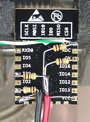
Opps - this is what the board looks like:

1 Like

While not necessarily cheaper, I prefer to use Lutron Pico Remotes as my button controller devices throughout the house. These do require a Lutron Smart Bridge PRO2 hub (~$100), so not exactly cheap. The Pico Remotes, however, are only about $15 a piece. The local LAN integration with Hubitat is very reliable and very fast. The Pico Remote battery is rated for 10 years and is replaceable.

Example of a Pico Remote

https://www.amazon.com/Lutron-3-Button-Wireless-Lighting-PJ2-3BRL-GWH-L01/dp/B00IZCQVO4

Pico Remotes can be wall mounted as well

https://www.amazon.com/Caseta-Wireless-Wallplate-Bracket-PICO-WBX-ADAPT/dp/B00JZRAFEA/ref=pd_bxgy_60_img_2/135-7427882-1286336?_encoding=UTF8&pd_rd_i=B00JZRAFEA&pd_rd_r=2114545e-9101-4fe4-838c-fd42b4d47b44&pd_rd_w=iGDH9&pd_rd_wg=apQh8&pf_rd_p=09627863-9889-4290-b90a-5e9f86682449&pf_rd_r=9802GVVBVK602VTHQZSR&psc=1&refRID=9802GVVBVK602VTHQZSR

And here is a table-top base that is nicely weighted and holds a Pico for easy access.

https://www.amazon.com/Caseta-Wireless-Pedestal-Remote-L-PED1-WH/dp/B003WGU2MU/ref=pd_sbs_60_t_1/135-7427882-1286336?_encoding=UTF8&pd_rd_i=B003WGU2MU&pd_rd_r=a4a1c1c3-ea52-4f9d-963a-7b74e2f5a7d5&pd_rd_w=RJ2w0&pd_rd_wg=bEZet&pf_rd_p=5cfcfe89-300f-47d2-b1ad-a4e27203a02a&pf_rd_r=9802GVVBVK602VTHQZSR&psc=1&refRID=9802GVVBVK602VTHQZSR

The Lutron Smart Bridge PRO2 hub can be found at

https://www.energyavenue.com/Lutron/L-BDGPRO2-WH

If you'd prefer to keep it simple, the SmartThings Zigbee button device is a very cost effective solution..

https://www.bestbuy.com/site/samsung-button-white/6265829.p?skuId=6265829&ref=212&loc=1&extStoreId=378&ref=212&loc=1&gclid=CjwKCAiA3abwBRBqEiwAKwICA1bqI_AVMSaXsozuiKu58xzVQgli98CCC-Y9XRWjt6eMxZZ_9NWSFxoCaZ0QAvD_BwE&gclsrc=aw.ds

As @Ryan780 mentioned, possibly a simpler design would be to simply send a "button1 pushed" event from the sketch, instead of toggling a contact sensor. This way you would truly be emulating a Hubitat "Button Controller" device. HubDuino supports button devices, which actually don't even create any child devices. The Parent Device is the "Button Controller" and generates the "pushed" and "held" events.

There is no reason to redesign your system at this time. If you'd like to switch to button devices, just let me know and I'll gladly tweak the sketch.

Have Fun and Happy New Year!

1 Like

ESP8266 Is wifi. The only zigbee equivalent would be the Xbee boards. But those are like $20-40 each. So, definitely not in the same price-range as the ESP boards.

As far as cheaper....if you had a custom board printed, and then bought a lion battery and the ESP module, how much did each of these single buttons run you? You can get the ERIA dimmer module, which is bascially 6 buttons in one for $20. That's less than $4 a button. I guarantee you spent more than that for your single buttons. Plus they are zigbee so they don't require your router or take up a space on your network. And the reaction time is a lot faster.

I've been aware of all of the options you both mentioned. I really do like the Lutron Pico, but I also have a huge amount of electronic components laying around, and in the last few hours I cranked out 5 little remote button devices. They work pretty well. There is of course a bit of a delay, but I'm okay with that - what was it that Wonka said? "The suspense is terrible, I hope it'll last." :slight_smile:

Ogiewon, I am interested in what a "Button Pushed" sketch would look like with deep sleep on an ESP. It would be cleaner. I think I just landed on the contact thing because it was the first thing that worked for me and I went with it.

As far as how much each button costs me - it really is in the $7 range. (to be clear - I don't have custom boards printed - they are just stock ESP8266-12F boards) All the parts individually are very low cost - mostly Chinese suppliers off ebay. And I enjoy a little soldering from time to time - so it is a joy to make them.

Like I said - if they come out with a low cost "zigbee-esp8622-ish-like" (note the "ish" - I do realize that ESP8266 is wifi only - but I would not be surprised to see something eventually come out along those lines) I'd switch over in a heartbeat. I do like the speed and low power of the zigbee stuff... but the boards are just crazy expensive considering what you can get an ESP board for!

Thanks for the help guys! Happy new year to you also!

What are you attaching the surface mount board to in order to solder components to it? It's not just the resistors you have on the back, is it? Your boards are going to last exactly one cycle of the battery. The ESP 8266 is very sensitive to voltage. It needs exactly 3.3 volts. It will start to drop out around 3. So, as soon as your lipo battery starts dropping, it won't work anymore. Plus, when your lipo is fully changed, the voltage is much higher than 3.3 volts. It's going to fry the board. Take a look at a NodeMCU or Wemos D1 Mini. Do you think all those extra electrical components are on there just for the fun of it? No, they have to be. These little buttons are really not going to last so you would have spent all this time for nothing.

And I don't understand how you get $7 per button. The board couldn't have been less than 3 or 4, even if you bought them from China. But then you had to buy the batters. And print the enclosure.

1 Like

This is the board I use: (There are holes and pads to solder to)

I use this little 3.3v regulator design:

They are about 10 for $1:

These batteries:

The 1/8th watt resisters, caps, and PLA filament are pennies.

My prototypes have been working pretty well so far. Here's hoping! :slight_smile:

2 Likes

HubDuino/ST_Anything supports Over The Air (OTA) updates on the ESP8266 boards. This does not work with your current sketch due to the deepSpleep. However, it wouldn’t be too difficult to tweak your sketch to only deepSleep if a GPIO pin were pulled either high or low. This would allow you to temporarily disable the deepSleep to allow for an OTA Update of the sketch running on the board. Afterwards, the board would resume its current behavior. Just an idea that might make it simpler for you to maintain these devices.

What about one of these? Samsung SmartThings Button: https://www.amazon.com/dp/B07F8ZFFQK/ref=cm_sw_r_cp_api_i_lVRcEbRYFZHAC

Looks like there is a used one via prime for $9.99. Each button can do 3 actions (push, hold, double click). They also double as temp sensors.

1 Like

The power regulator you are using requires at least an input voltage of 4.3v to regulate a 3.3v output. If you look at the discharge curve of a 18650 battery, it drops below 4.3v very, VERY early in it's life-span. It only uses 4-8uA and the ESP only uses about 20uA in deep sleep. But that isn't zero. It's still going to use some of the power of your battery, further shortening the time it takes to get below 4.3v.

The regulator also maxes out at 250mA. The ESP8266 is known to pull 320mA at startup. And since you are going to be doing startup every time you press the button, this is going to put a strain on your power regulator possibly burning out rather quickly.