Years ago, my first experience with a Schlage Camelot Z-Wave lockset was excellent: it paired easily and operated reliably. Recently, after replacing two sliding glass doors with French doors, I bought two more Schlage Camelot Z-Wave deadbolts based largely on that experience. The new locks, however, performed very differently. Pairing them while installed on the rear doors was nearly impossible, so I had to remove them and place them near the hub to get them connected. Once reinstalled on the rear doors, remote operation and lock-status reporting were inconsistent at best and sometimes unavailable. Their battery life was also far worse than that of the original lock.
Through Hubitat support, I learned that many others had experienced similar problems with Schlage Z-Wave locks. Their reliability was poor enough that Schlage locks were removed from Hubitat’s “Compatible Devices List,” where, to this day, they remain absent. Why, then, was my first lock so dependable while the two newer ones were nearly unusable? Distance seemed the obvious explanation. The original lock on the front door was within 10 feet of the hub, with only one wall between them. The two new locks were more than 30 feet away on the rear doors, with several walls in between. Yet other Z-Wave devices in that area worked well, some from even greater distances.
The locks clearly transmitted a weaker signal than nearby devices, but why? Their internal components were nearly identical, so the key difference appeared to be the Schlage lock’s built-in antenna: it was too short. In the United States, Z-Wave operates around 912 MHz, where a resonant quarter-wave antenna is approximately 3.24 inches long. I measured the lock’s printed-circuit antenna at about 2.5 inches. At 912 MHz, that three-quarter-inch difference can significantly reduce antenna efficiency. After soldering a three-quarter-inch wire extension to the antenna tip, I experienced no further connectivity problems. As an added benefit, battery life became comparable to that of the lock near the hub.
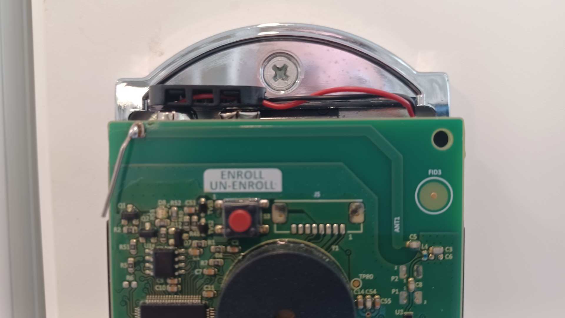
If you have an unreliable Schlage Z-Wave lock—or one you set aside after giving up on it—consider trying this fix. The antenna is the uppermost printed-circuit trace along the board’s top front edge. Scrape away a small patch of the green protective coating at the trace’s lower left end, then solder a three-quarter-inch wire to the exposed copper. Position the wire downward to extend the built-in antenna. A short piece of insulated, single-strand telephone wire is likely best because the insulation reduces the risk of the extension contacting another circuit-board component. Good luck.
This is a great find...are you able to share your board's photo? I'm a visual learner and would like to confirm I am performing the same operation as you...and that my board looks similar.
an awesome find, please do share some pictures of how you soldered the wire to the board as i am visual learner as well. I have the original lock and it would be great to be able to test this on my original lock. My C5 can lock and unlock my door without an issue however, I run into continuing issues trying to add or remove codes from my lock the code manager fails and trying to enter the codes into the lock driver directly also fails. I’m wondering if this may improve the signal quality of my original lock and intern make programming codes more efficient.
This is fairly normal due to the whisper encryption.
This is generally because a repeater isn't near by. For my own locks I have ring repeaters very close to all 3 doors in my house. This solves the issues completely (or any good z-wave switch right by the door should do). I also recommend switching to z-wave JS.
The reason they were removed from the compatibility list is due to the firmware. Anything before 7.10 is a crap shoot. Though even older ones seem to work better with JS
The antenna extension is pictured above. Use a small flat screwdriver or a small sharp blade to scrape away the protective green coating, and expose the copper trace, at the left most tip of the printed circuit antenna. Before soldering it in place, use small needle nose pliers to bend the 3/4" wire in such a way that it's final position ends up parallel to but slightly above the surface of the circuit board. As evidenced by the wire's shadow in the picture. Use needle nose pliers or small forceps to hold the wire in position while soldering and until the molten solder sets. The cooling process only takes a few seconds to complete. The finished solder joint should look bright and shiny. If it turns to a dull silver color while cooling, it's an undesirable "cold solder joint". In that case just reheat it and try again. As mentioned in the original post, small single strand insulated wire would probably be preferable as the insulation would minimize the chance of the extension ever coming in contact with other circuit board components.
Does the additional wire have to be 3/4" or can I make a 2" piece perform the same or better? The picture clears everything up in my mind so thank you very much!
My thought was add the wire but have align over the trace so its basically doubling back in the same direction. Again, not an antenna expert so just thinking out loud and wondering if you've a clue to spare...
That length of 0.75" is based on the existing trace antenna on the lock being 2.5". So the total length would be 3.25", which is the length of a quarter-wave antenna for 912 MHz.
For 912 MHz, a half-wave antenna would ~6.5" and a full-wave antenna would be ~12.9".
So, while soldering on a 2" extension would be undesirable, you could consider adding a 4" extension - to make a half-wave antenna.
I haven't had a Schlage z-wave deadbolt in almost a decade. But if I were doing this, I would use 18 gauge solid copper conductor - something like thermostat wire, and I would leave it in the wire jacket as @joepollet recommended.
Interesting find. The geometry of the PCB traces is a big part of the antenna design, especially at 900MHz. I have to believe Schlage had RF engineers designing the element through simulation and prototyping to ensure best possible gain and pattern. The 90 degree bend and the 45 degree transition portion are all part of a microwave strip line (as are the PCB material type and any ground plane on the other side of the PCB) and would have been simulated. It is far more complicated than simply the length of a wire. So it is a bit surprising this hack works so well.
RF is a strange beast, cool find. Another strike on Schlage for a weak Z-Wave offering. I gave up on them months ago and went to Kwikset due to software issues. I have a new BE469 on a shelf collecting dust....