When I turn the breaker off, everything goes off. That was my first step as to not get myself toasted
That's good new. That means you can use the neutral and line from the outlet. As for load. it will be on one of the wire on the dark terminal of the switch. One of the switch dark terminal will be your load and the other one will be your line.
The inside switch has a dimmer next to it for a nearby chandelier. It’s just a 2 wire + ground.. i mention in case it could be used in the rewire.
I’m a little lost on the next steps, not sure if you have time to clarify any further, but it’s appreciated either way.
If both switches control the same light, they have to meet up somewhere, right? I mean, they don't control it by magic. LOL ![]()
I'm thinking the best approach is to get as much information as we can from the wires you have in the two boxes.
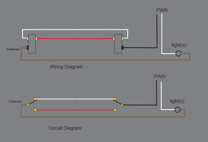
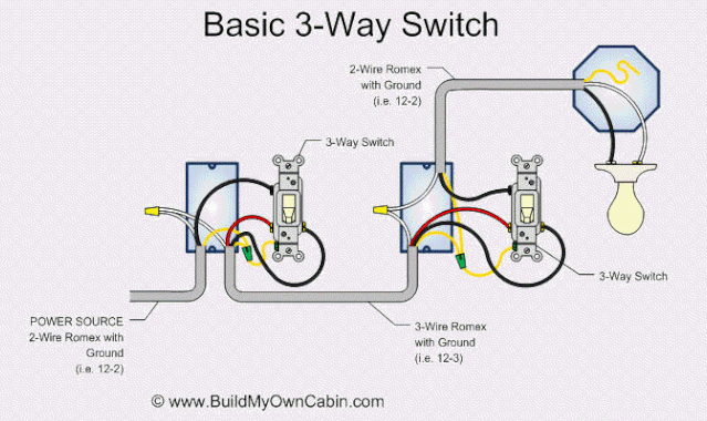
It might help if you understood the basics of 3 way switching:
They are really easy to understand once you look at the switches as SPDT type.
See this video.... 3 way ... let me know if you have any questions. Note the circuit on the right does not apply to your application. Try to ignore it.
I have never seen the type of switch with the two screws on the top. I can only guess on the function. Can you measure it with an ohmmeter (with the wires disconnected) and tell me which is the common (see vodep am ,omite 1:42)?
John
If you're going to test resistance, just make sure the breaker is off!!!
That's a great video....does a great job of describing the principles of a SPDT switch.
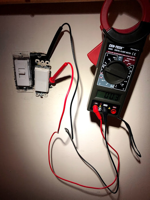
Ignore the traveler wires. Put the meter to AC selector and just put one of the meter probe on a dark terminal of a switch and the other meter probe on ground. With the light bulb off and the dark terminal with no voltage is your load. The dark terminal with 110VAC regardless of light on or off is your line.
Thanks, for some reason it’s tough to grasp the three way setups.. it’s easy to understand in diagrams but once I start relating it to my scenario I get lost. Will get back on the testing that @Navat604 suggested.
Its easy to get lost. I find drawing it on a pad makes it easier for me.
What Navat604 is asking you to determine is which of the switch commons is going to power and which is going to the bulb.
I don't know if the switch in the garage has a black terminal. I'll guess not since you didn't mark it on your drawing. It would be best if you could determine which is common on that switch. I would assume it is the bottom screw (not shown), but I would not bet my hardware on that assumption.
John
I’m going to double check the garage switch tomorrow evening for that. Thanks for the help, all..
While your are checking in the garage, Look for some junction box (could be with another light or outlet) that might be the junction of the switch boxes.
If there is one wire to the light
and only one wire to the inside switch
and only one wire to the garage switch
There MUST be a jucntion box somewhere to make the power and switch connections.
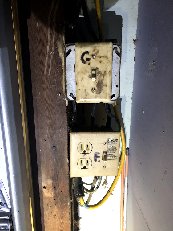
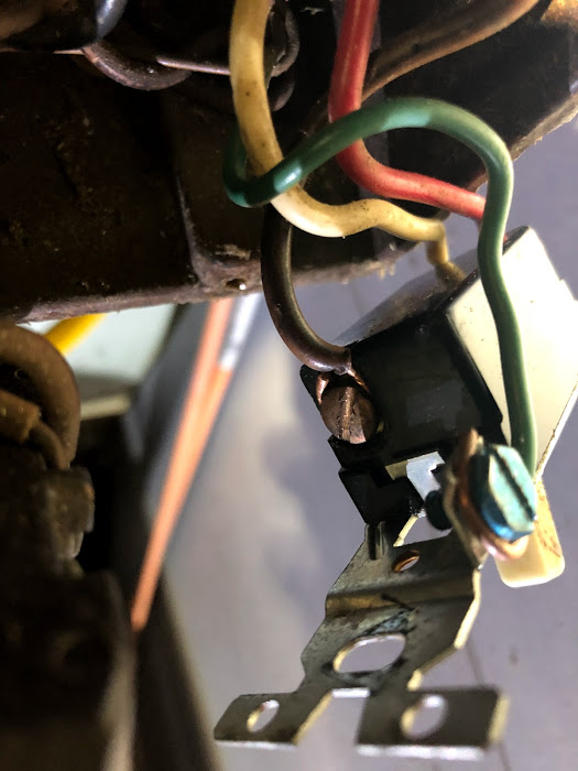
Did some homework tonight and have some better pictures to share:
Bottom box switch controls the flood light I'd like to control. Switch above is for the garage interior light.
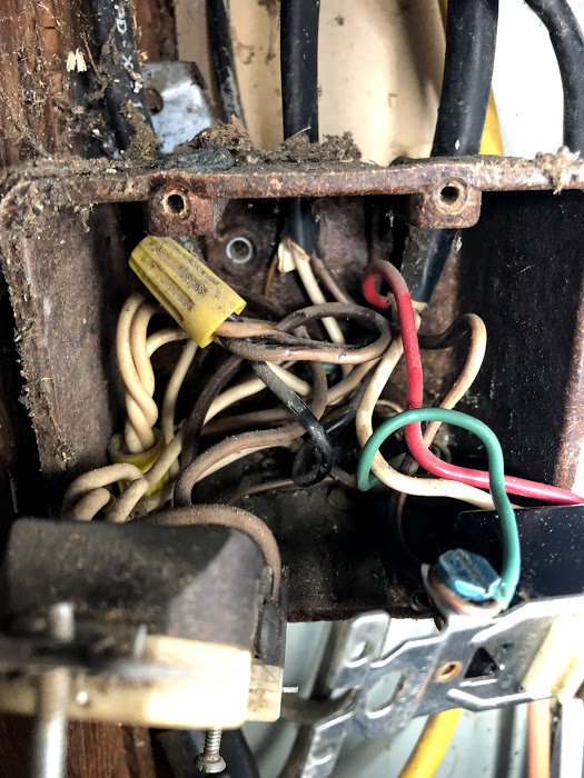
Looking closer this time, I realized I made a mistake on my initial look. The bottom brown colored wire is actually coming from a separate 2 wire Romex. Doh, my bad.. It is not from the above box and leaves the garage in a similar spot that the switch wires do.
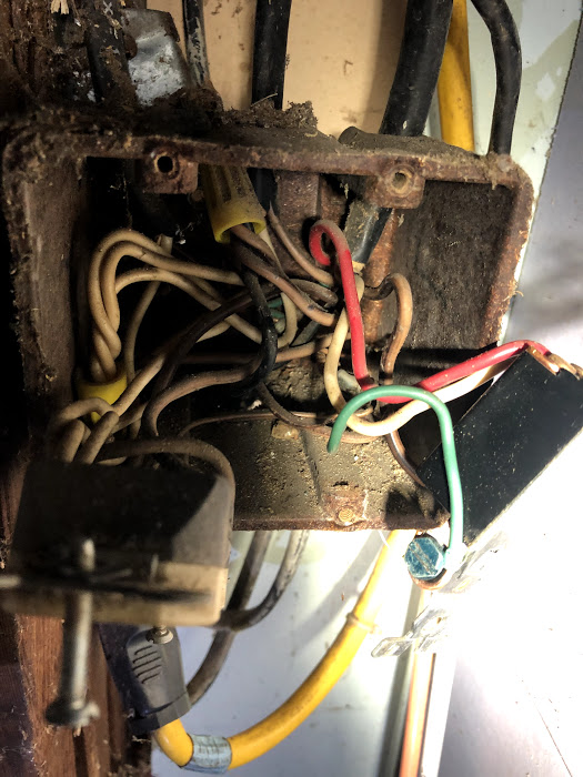
I think this finding will change the next steps, but I proceeded to try and do the testing that @Navat604 suggested.
The bottom terminal on the garage switch does not appear to be a darker screw. This is likely original 1972 wiring, so not sure if the switches were different at that point:
Garage switch testing:
Bottom screw to ground, inside switch as-is:
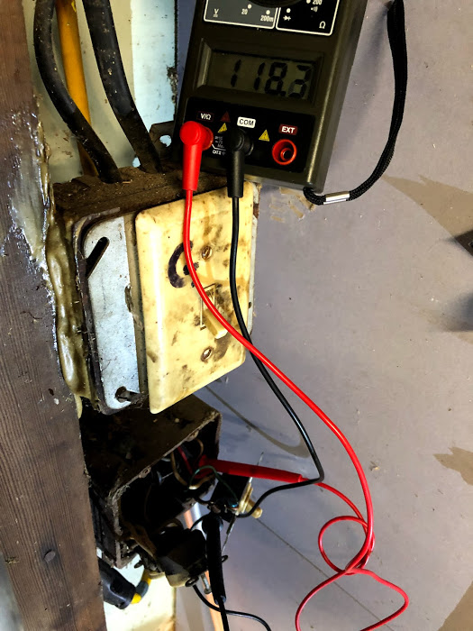
Bottom screw to ground, inside switch flipped:
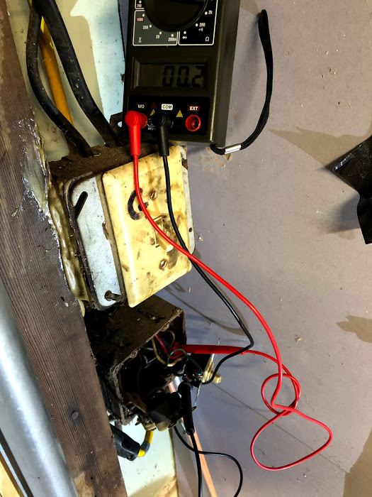
Inside switch, black terminal to ground:
Inside switch flipped black terminal to ground:
I have everything still exposed and a bit of time before bed to experiment further if anyone has suggestion. Again, apologies for the incorrect diagram. I must have been rushing in the dark, cold garage 
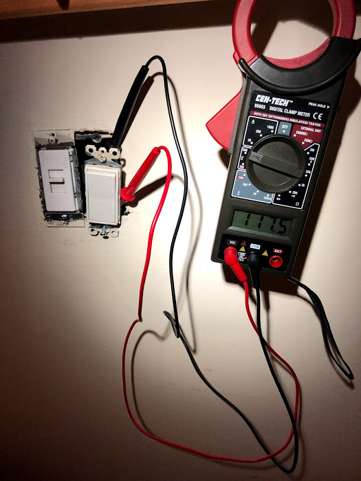
One correction on the inside switch test, the black screw has 120v regardless of the garage switch position.
Power on always is a good clue.
Is there a red wire on that inside? Measure it. Power should be on it when the switch is in one position or the other. With the red hot, go to the other switch and verify the red is hot.
Then come back inside, flip the switch, verify red inside is not hot, go out and check red again, should also be not hot. That would make the red your traveller.
Hot on the Inside switch and the light being closest to the garage switch, implies you have this configuration:
Red wire is connected to the black screw inside. It flips from 120 to 0v when I flip the same switch. It stays 120 when I flip the garage switch. Does that make sense? I can complete all your suggested testing but want to be sure I’m on the right track
It's important to know that you have a wire that goes between the Inside and Garage boxes. Proceed with testing.
Do you have the New Switches - both the active one and it's Add On?
Got it. I tested and I believe this lines up with your assumption. With the inside red wire hot, the garage red is hot. Flipping the switch inside, the garage red wire is 0v. And again, flipping the garage switch had no impact on the inside red.
And I only have the primary GE switch as of now. I can pick up the add on this weekend if there’s a chance this can work on my setup
You have Hot and Neutral in the Garage box and you have the lamp romex too. With only one switch, I think you're looking at just installing it into the Garage.
You'll be ignoring the Inside switch for now.
Turn off the Circuit breaker, and verify there is NO HOT inside the garage box, including the receptacle.
Remove the wires from the old switch. wirenut or tape the white and red to prevent a short.
Wire the GE across the Receptacle: White on the receptacle goes to the GE's Neutral screw. Black on the receptacle goes to Line on the GE.
Use the "brown" wire off the old switch to the Load screw of the GE.
That should be it. Circuit breaker back on and the GE should physically be able to control the light. Join it to the Hub and you should be able to remotely control the light.
When you do finally get the Add-On, after turning off the circuit breaker, disconnect all three wires from the Inside switch. You won't need the Hot, you won't need the other either. You only need Red and a Neutral, which I assume is on the 2nd switch in the Inside box.
You'll wire Red in the garage to the 4th screw, the one that they put tape over. Then Inside, you'll wire red to Traveler on the Add-On, and neutral to N on the GE.
Wirenut the left over wires, especially that HOT one. If it's just a "bridge" from the 2nd switch, just remove it.
2 Likes

